Your shopping cart is empty!
They are the same. The “QSFP” form factor was originally defined for <10G speeds. When it was adopted for 40G, the name became QSFP+ to denote the higher aggregate performance. The same “QSFP” form factor was later adopted for 100G but the electrical interface had to be upgraded to handle 25Gbps/lane. The electrical interface for 100G can handle up to 28Gbps, hence the engineering and industry name is QSFP28. JTOPTICS refers to the 100G form factor as “100G QSFP” to avoid any confusion.
The JTOPTICS QSFP-100G-ZR4 supports link distances up to 80km. A minimum of 12dB attenuation is required to prevent permanent damage to the receiver - refer to the optics datasheet for optical specs. The QSFP-100G-ZR4 is supported on a limited set of platforms – refer to the Transceiver and Cable Guide for supported platforms. The QSFP-100G-LR4 supports links up to 10km over duplex single mode fiber. Enabling FEC with QSFP-100G- LR4 optics on JTOPTICS switches can allow for links beyond 10km with single mode fiber.
Like the QSFP-100G-SWDM4 transceiver described above, the JTOPTICS QSFP-100G-SRBD transceiver also provides 100Gbs bandwidth over standard duplex multi-mode fiber. However, unlike the SWDM4 transceiver (which transmits 4 x 25Gbps wavelengths out of the Tx port, and receives 4 x 25Gbps wavelengths on the Rx port), each optical port on the SRBD contains both a transmitter and receiver, running at full duplex 50Gb/s over a single fiber. The two ports of the QSFP-100G-SRBD provide an aggregate 100Gb/s of bandwidth. The QSFP- 100G-SRBD is supported on all JTOPTICS QSFP 100G ports, and can be used for links up to 70m of OM3 or up to 100m of OM4 multi-mode fiber.
No. The 100G QSFP form factor has just 4 electrical lanes, which is not enough to support 10 lanes of 10G electrical interface. A 100G QSFP can only support a 4x10G or 4x25G electrical interface, which can be used as 4x10GbE or 4x25GbE, but not 10x 10GbE.. As a result the 100G QSFP SR4 cannot interoperate with SR10 based 100GbE transceivers. A complex design with a reverse gearbox (4x25G to 10x10G) can achieve this but results in expensive and power hungry optics.
Breakout mode refers to running a 100G port as 4 separate channels of 25GE. Transceivers or copper cables that enable optical or electrical breakout allow one 100G QSFP100 port to connect to four physically separate 25G links. When breaking out a single 100G port to 4x 25G links, care must be taken to use the same Forward Error Correction (FEC) mode on both ends of the link to ensure link-up. JTOPTICS transceivers and copper cables that support 100G to 4x25G breakout are listed below.
The 100G-DR/FR/LR transceivers can be plugged into any JTOPTICS 100G QSFP port. The electrical connector interface is 4 x 25G NRZ – the same as all existing ‘legacy’ 100G QSFP modules. The optical output is a single wavelength (or “lambda”) 100Gbit/s PAM-4 optical signal. The 100G-DR/FR/LR modules include a gearbox chip to convert the 4 x 25G NRZ electrical signals to a 1 x 100G PAM-4 optical signal. This is in contrast to legacy QSFP100 modules (such as a CWDM4 or LR4 100G module), which have 4 x 25G NRZ optical wavelengths multiplexed onto one fiber.
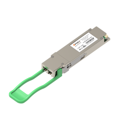
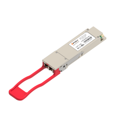
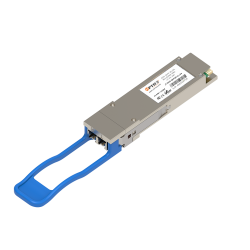
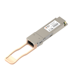
100G QSFP28 transceivers are high-speed, compact optical transceivers designed for data centers, enterprise networks, and high-performance computing environments. These transceivers support data rates up to 100 Gigabits per second (Gbps) and are commonly used for high-density 100G Ethernet and InfiniBand applications.