





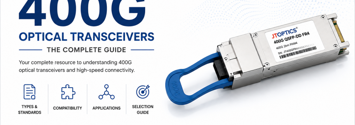
400
Gigabit Ethernet has become the dominant high-speed interconnect standard for
AI infrastructure, hyperscale cloud fabrics, and next-generation telecom
transport, occupying the position that 100G held a decade earlier as the
workhorse speed of large-scale networking. The transition from 200G to 400G is
not simply an incremental doubling of bandwidth; it reflects a broader shift in
how data center and AI networks are architected, driven by the scale of modern
GPU clusters, the bandwidth appetite of distributed AI training, and the
maturing of PAM4-based electrical and optical interfaces first standardized at
200G.
Where
NVIDIA NVLink and similar proprietary interconnects handle the tightest-coupled
GPU-to-GPU communication within a server or rack, 400G Ethernet (and
increasingly InfiniBand at comparable rates) carries the scale-out fabric that
connects GPU nodes, storage systems, and switches across a data hall. Cloud
providers use 400G as the standard spine and increasingly leaf speed in new
fabric builds. Storage systems built around NVMe over Fabrics rely on
400G-class links to avoid becoming the network bottleneck ahead of increasingly
fast storage media. 5G core and aggregation networks, along with metro and
long-haul data center interconnect (DCI) links, have adopted 400G coherent optics
as a mature, cost-effective way to move large volumes of traffic between
facilities.
This
guide is the third in JTOPTICS® technical series on optical transceivers,
following the Complete Guide to 100G Optical Transceivers and the Complete
Guide to 200G Optical Transceivers. It follows the same technical depth and
structure while going further into the architectural complexity that 400G introduces
dual form factors (QSFP-DD and OSFP), a wider range of module types including
coherent 400ZR/400ZR+ optics, deeper PAM4 signal theory, and the emerging role
of silicon photonics.
Evolution
from 10G to 1600G
Why 400G Became the Dominant Next-Generation Speed
Several
converging factors made 400G, rather than an intermediate step, the primary
target speed for large-scale network refreshes. AI training clusters
interconnecting hundreds or thousands of GPUs generate enormous east-west
traffic volumes during distributed training, where gradient synchronization
across nodes is highly bandwidth- and latency-sensitive; insufficient network
bandwidth directly extends training time and reduces GPU utilization
efficiency. NVIDIA's NVLink ecosystem handles intra-server and some intra-rack
GPU interconnect, but the broader scale-out fabric connecting GPU servers,
storage, and switches across a data hall still relies on Ethernet (or
InfiniBand) at 400G and higher rates. Hyperscale cloud operators building new
regions or refreshing existing fabrics have standardized on 400G spine
connectivity, with many also deploying 400G at the leaf layer for the
highest-density server racks. Storage fabrics built on NVMe over Fabrics
increasingly require 400G-class links to avoid network-imposed throughput
ceilings. 5G core and transport networks, along with metro and long-haul DCI,
have found 400G coherent optics (400ZR and 400ZR+) to be a cost-effective way
to substantially increase capacity per wavelength compared to earlier 100G
coherent generations.
IEEE
Standardization
400
Gigabit Ethernet is defined primarily under IEEE 802.3bs (the original
200G/400G Ethernet standard, ratified in 2017), with subsequent amendments
extending and refining the physical layer specifications. IEEE 802.3cd
contributed additional 50G-per-lane PAM4 physical layer work relevant to 400G's
electrical lane building blocks. IEEE 802.3ck defined 100G-per-lane electrical
interfaces (100 Gbps per lane using PAM4), which underpin many
current-generation 400G modules built on 4x100G PAM4 architecture. IEEE 802.3cu
addressed single-mode fiber physical layer specifications including
400GBASE-DR4. IEEE 802.3db addressed multimode fiber physical layer
specifications using 100G-per-lane signaling. IEEE 802.3df, a more recent
amendment, extended physical layer specifications to 800 Gigabit Ethernet,
reflecting the continuation of this lane-based scaling philosophy beyond 400G.
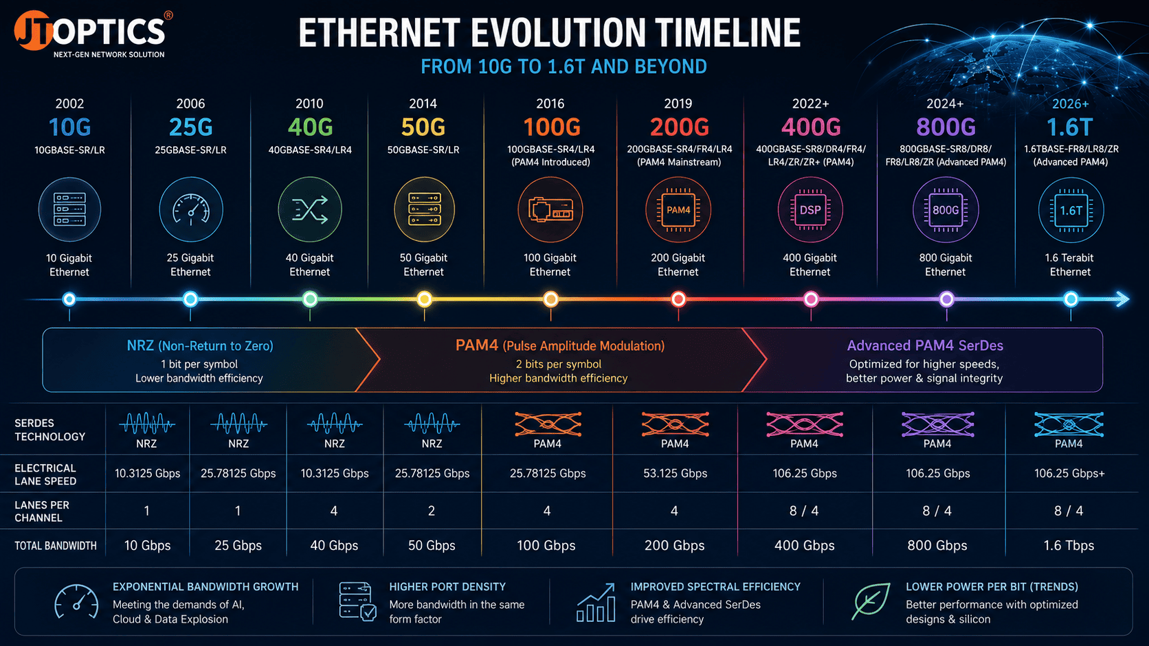
Lane
Evolution: 4x100G PAM4 and 8x50G PAM4
400G
Ethernet has been implemented using two principal lane architectures. The
earlier and still widely deployed approach uses 8x50G PAM4 lanes, consistent
with the 200G generation's per-lane rate, simply doubling the lane count from
four to eight. The newer approach uses 4x100G PAM4 lanes, leveraging improved
SerDes technology defined under IEEE 802.3ck to carry 100 Gbps per lane,
halving the lane count required for the same aggregate 400G rate. This shift
mirrors the earlier transition from 100G's 10x10G lanes to 4x25G lanes, where
SerDes improvements progressively reduced the number of lanes needed per given
aggregate rate, simplifying host-side routing and enabling higher-density
switch ASIC designs.
SerDes
Evolution and Breakout Architecture
Because
400G modules can use either eight or four host-side electrical lanes depending
on generation, they support flexible breakout configurations. An 8-lane (8x50G)
400G port can commonly break out into two 200G ports or four 100G ports, while
newer 4-lane (4x100G) 400G interfaces are more naturally suited to breakout
into four 100G ports using single-lane-per-port electrical mapping, or two 200G
ports. This breakout flexibility is central to how hyperscale operators
maximize switch port utilization when connecting a mix of legacy
100G/200G-capable servers and newer 400G-native equipment to the same switching
platform.
Relationship
with 800G
The
same 100G-per-lane PAM4 SerDes generation that enables 4-lane 400G modules also
underpins 800G modules, which use eight lanes of 100G PAM4 rather than four.
This shared electrical foundation means 800G switch ports frequently support
breakout into two native 400G ports, continuing the lane-based building-block
philosophy that has characterized Ethernet's speed progression since the
introduction of PAM4.
What Is a 400G Optical Transceiver?
A 400G optical transceiver is a pluggable module that converts electrical signals from a host switch, router, or network interface card into modulated optical signals for fiber transmission, and performs the corresponding reverse conversion on receive, at an aggregate data rate of 400 gigabits per second.
Electrical
interface: Depending on module generation, the host-side electrical
interface presents either eight lanes of approximately 53.125 Gbaud PAM4
(400GAUI-8) or four lanes of approximately 106.25 Gbaud PAM4 (400GAUI-4),
consistent with the 8x50G and 4x100G architectures described above.
Optical
interface: The optical interface, wavelength plan, number of optical
lanes, connector type, and reach vary substantially by module type, ranging
from short-reach multimode parallel optics to coherent long-haul interfaces, as
detailed in the module type sections below.
Optical
engine: As with 100G and 200G modules, the optical engine performs
electrical-to-optical and optical-to-electrical conversion using a laser driver
and laser diode on transmit, and a photodetector, TIA, and associated receiver
circuitry on receive. At 400G, the optical engine is more frequently built
using silicon photonics integration, particularly in high-volume hyperscale
deployments, as discussed in its own section below.
Signal
flow, PAM4 generation, and DSP: Electrical data arriving from
the host is mapped into PAM4 symbols, encoded, and used to drive the laser (or
lasers, in multi-wavelength/multi-lane designs). A DSP performs equalization,
PAM4 encoding/decoding, and FEC processing on both transmit and receive paths,
functions that are, if anything, more demanding at 400G's higher per-lane baud
rates than at 200G, given the further-reduced timing and amplitude margins
involved.
Form
Factors
QSFP-DD
QSFP-DD (QSFP Double Density) extends the QSFP mechanical family by adding a second row of electrical contacts, doubling the number of host-side electrical lanes to eight while retaining a similar overall footprint and cage compatibility approach to QSFP28/QSFP56. QSFP-DD modules are available in both 8x50G PAM4 and 4x100G PAM4 electrical variants. Typical power dissipation for QSFP-DD 400G modules ranges from approximately 8 to 14 watts depending on optical design, with passive DAC variants drawing negligible power. QSFP-DD's principal advantage is very high port density, since its footprint is only marginally larger than QSFP28/56, allowing switch vendors to pack a large number of 400G-capable ports into a single-rack-unit switch. Its main limitation relative to OSFP is a somewhat tighter thermal envelope, since the QSFP-DD body has less surface area for heat dissipation than OSFP.
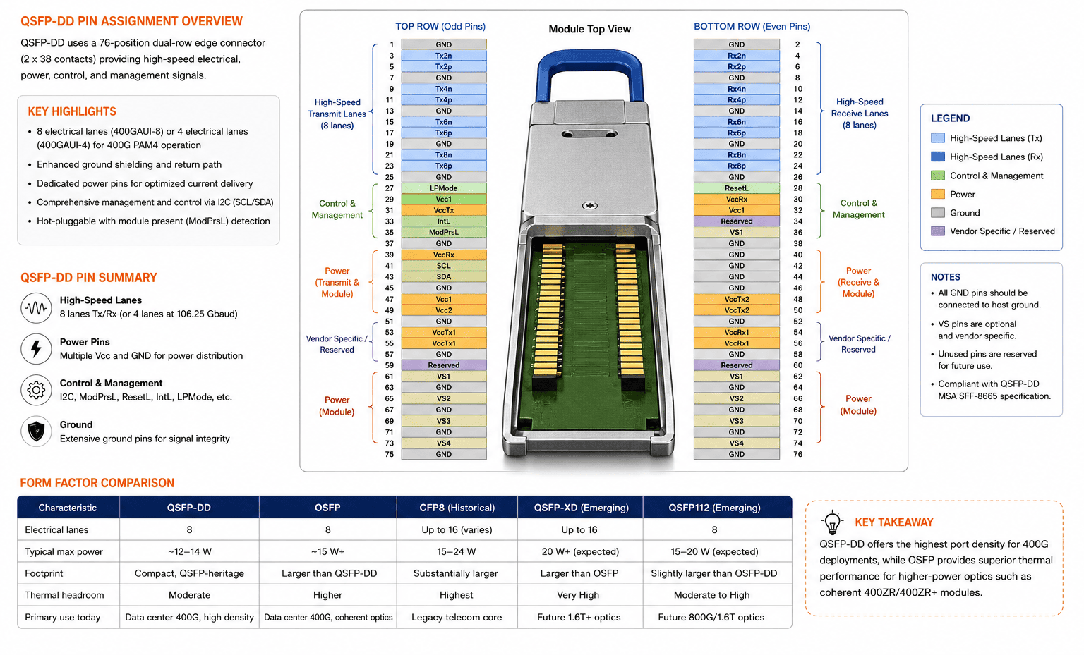
OSFP
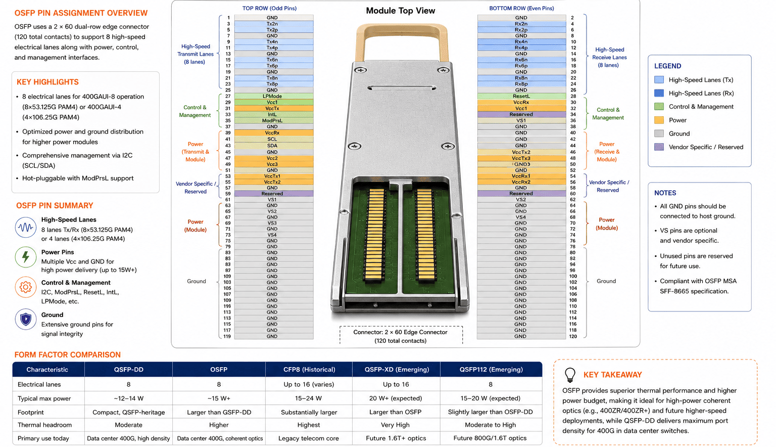
OSFP
(Octal Small Form-factor Pluggable) is a larger, purpose-built
form factor for 400G and higher-speed optics, also supporting eight electrical
lanes, but with a physically larger housing than QSFP-DD, providing greater
surface area for heat dissipation, an advantage for higher-power modules such
as coherent 400ZR/400ZR+ optics. OSFP typically supports higher maximum power
dissipation, commonly cited up to around 15 watts or more for demanding module
types, compared to QSFP-DD's tighter thermal budget. OSFP's larger footprint
reduces port density slightly relative to QSFP-DD on a given faceplate width, a
trade-off many hyperscale operators accept in exchange for the thermal headroom
needed for higher-power coherent and future higher-speed optics. OSFP modules
require an OSFP-specific cage and are not mechanically interchangeable with
QSFP-DD, though some switch platforms offer OSFP ports with adapters supporting
QSFP-DD modules at reduced pin utilization.
OSFP-XD
and QSFP112 (Emerging)
OSFP-XD is an
emerging form factor extending the OSFP mechanical concept to support higher
lane counts and future speed grades beyond 800G, relevant primarily to
next-generation 1.6T planning rather than current 400G deployments. QSFP112
is a proposed evolution of the QSFP family supporting higher per-lane
electrical rates (up to approximately 112 Gbaud), positioned as a potential
higher-density alternative for future 800G and 1.6T applications. Both are
mentioned here for completeness and forward context rather than as current
mainstream 400G solutions.
Form
Factor Comparison Table
|
Characteristic |
QSFP-DD |
OSFP |
CFP8 (Historical) |
|
Electrical lanes |
8 |
8 |
Up to 16 (varies) |
|
Typical max power |
~12–14 W |
~15 W+ |
15–24 W |
|
Footprint |
Compact, QSFP-heritage |
Larger than QSFP-DD |
Substantially larger |
|
Thermal headroom |
Moderate |
Higher |
Highest |
|
Primary use today |
Data center 400G, high density |
Data center 400G, coherent optics |
Legacy telecom core |
Internal
Architecture
The
internal architecture of a 400G transceiver builds on the same component
categories present in 100G and 200G modules, with additional complexity
reflecting higher lane counts, higher baud rates, and, in many designs,
integrated silicon photonics.
The
laser driver shapes PAM4 drive current for the laser source, with tighter
linearity requirements at 400G's higher baud rates. Laser technology choices
mirror earlier generations but skew toward higher-performance sources: VCSELs
remain used in short-reach multimode designs such as SR8, DFB lasers serve
cost-optimized single-mode designs, and EML (electro-absorption modulated
lasers) are used extensively in longer-reach single-mode designs such as FR4
and LR4. Increasingly, silicon photonics platforms integrate multiple optical
functions, including modulators and sometimes lasers via hybrid integration,
onto a single photonic integrated circuit, discussed further in its own section
below.
Optical
multiplexers and demultiplexers combine or separate individual wavelength or
lane signals within WDM-based modules such as FR4 and LR4, routing four (or
more) distinct wavelengths onto or off a shared fiber pair. On the receive
side, PIN photodiodes and APDs serve the same sensitivity-versus-cost trade-off
role described in earlier generations, with APDs favoured for longer-reach
designs requiring greater receiver sensitivity.
The DSP is substantially more capable in 400G modules than in earlier generations, incorporating a PAM4 encoder and PAM4 decoder, an equalizer performing both linear and, in more advanced designs, decision-feedback equalization to compensate for channel impairments, and FEC encoding/decoding. CDR (clock and data recovery) circuitry underlies the DSP's timing recovery function. An EEPROM stores vendor and calibration data, while an MCU manages module initialization and host communication, increasingly via CMIS, which by the 400G generation has become the standard management interface across essentially all mainstream module types, given its capability to manage the more complex configuration state of DSP-equipped, multi-lane, PAM4-based optics.
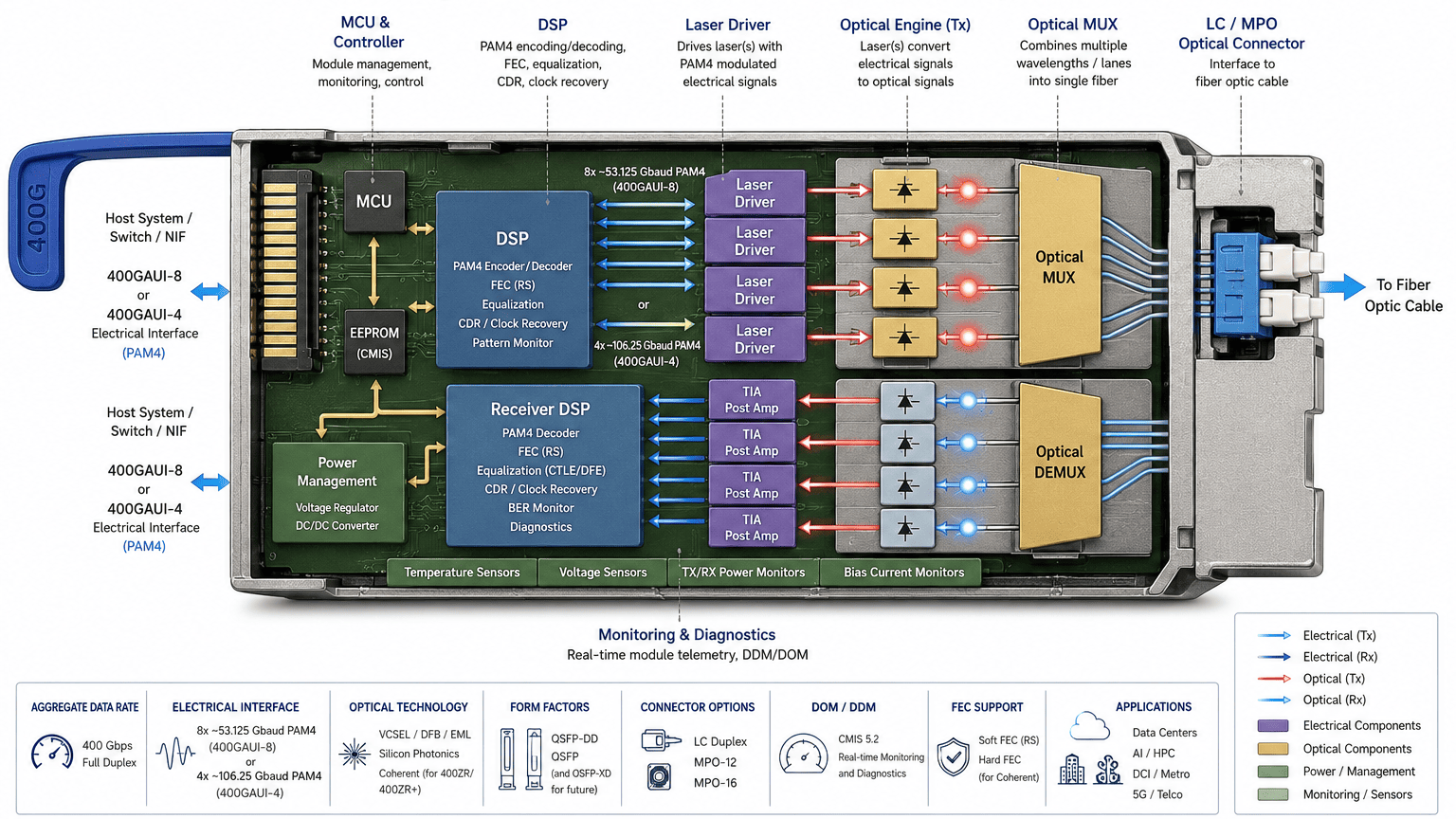
Power
management circuitry must regulate a wider range of supply rails across more
numerous active components than in 100G/200G designs, and thermal management,
including a substantial heat sink integrated into the module housing
(particularly pronounced in OSFP designs, which have more surface area
available), is a first-order design consideration given that 400G modules can
dissipate well over 10 watts in continuous operation. PCB layout must carefully
manage high-speed differential trace routing across eight or four lanes at 400G
baud rates, where via placement, trace length matching, and impedance control
materially affect signal integrity. The host edge connector follows the QSFP-DD
or OSFP MSA.
400G
Module Types
400GBASE-SR8,
standardized under IEEE 802.3cd/802.3bs, uses eight parallel optical lanes,
each carrying approximately 53.125 Gbaud PAM4, transmitted over multimode fiber
via an MPO-16 connector (accommodating sixteen fibers: eight transmit, eight
receive). It operates at approximately 850 nm using VCSEL laser sources. Over
OM4 multimode fiber, 400GBASE-SR8 typically supports a maximum reach of
approximately 100 meters, with reduced reach over OM3. SR8 is used for the
shortest intra-data-center links, particularly within or between adjacent
racks, where its VCSEL-based design keeps cost per port relatively low compared
to single-mode alternatives, at the expense of requiring more fiber strands per
link than WDM-based options.
400GBASE-DR4,
standardized under IEEE 802.3cu, uses four separate single-wavelength optical
lanes at approximately 106.25 Gbaud PAM4 each (aligned with the 4x100G
electrical architecture), transmitted over single-mode fiber via an MPO-12
connector without wavelength multiplexing, operating near 1310 nm. It supports
a maximum reach of approximately 500 meters over single-mode fiber, making it a
common choice for point-to-point single-mode links within a data center where
SR8's multimode reach is insufficient but full WDM-based FR4/LR4 reach is
unnecessary.
400G
DR4+
400GBASE-DR4+
(sometimes referred to in industry usage as an extended-reach DR4 variant)
extends DR4's basic architecture with improved optical budget margins,
supporting reach up to approximately 2 kilometres in some vendor
implementations, positioning it between standard DR4 and FR4 in terms of both
reach and typical cost. DR4+ is not always formally distinguished from DR4
under a single universal specification and should be evaluated against specific
vendor datasheets to confirm exact reach and compliance claims.
400GBASE-FR4,
standardized under IEEE 802.3cu, multiplexes four CWDM wavelengths (typically
in the 1270–1330 nm range) onto a single fiber pair using an LC duplex
connector, with each wavelength carrying a PAM4-modulated signal at
approximately 106.25 Gbaud. FR4 uses EML laser sources and supports a maximum
reach of approximately 2 kilometres over single-mode fiber, making it well
suited to data center interconnect applications and longer intra-campus links
where LC duplex infrastructure is preferred over parallel MPO cabling.
400GBASE-LR4,
also standardized under IEEE 802.3cu, follows the same WDM-over-LC-duplex
architecture as FR4 but is engineered for longer reach through higher-power EML
lasers and tighter optical budget specifications. LR4 supports a maximum reach
of approximately 10 kilometers over single-mode fiber, suited to metro-scale
connectivity and longer campus or building-to-building links.
400G
ER8 (Where Applicable)
400GBASE-ER8,
where implemented, extends the eight-lane WDM/parallel architecture concept to
substantially longer reach, generally in the range of 30 to 40 kilometres,
intended for metro and extended campus applications. ER8 implementations are
less common in mainstream data center deployments than SR8, DR4, FR4, or LR4,
and vendor-specific implementation details should be confirmed against current
datasheets given more limited standardization consensus at the time of writing
compared to the other 400G module types.
400G
ZR
400ZR
is an OIF-defined (rather than IEEE-defined) specification for coherent optical
transceivers supporting approximately 400 Gbps over a single wavelength using
advanced coherent modulation (typically 16-QAM), intended for point-to-point
DCI applications at distances up to approximately 80 to 120 kilometres without
external optical amplification, depending on fiber conditions. 400ZR modules
integrate a coherent DSP performing carrier recovery, chromatic dispersion
compensation, and polarization mode dispersion compensation, functions not
required in direct-detect PAM4 modules such as SR8, DR4, FR4, or LR4. 400ZR is
available in QSFP-DD and OSFP form factors, allowing it to be plugged directly
into standard data center switch or router ports designed for those form
factors, a significant advantage over earlier-generation coherent optics that
required dedicated line cards or transponder chassis.
400G
ZR+
400ZR+
(also referred to in various vendor and forum contexts as OpenZR+) extends the
base 400ZR specification with additional optional capabilities, including
support for longer reach through optical amplification, flexible baud rates and
modulation formats (allowing operators to trade reach for capacity), and, in
many implementations, support for lower rates such as 100G or 200G per
wavelength alongside 400G, providing greater deployment flexibility across
varying distance and capacity requirements. 400ZR+ is generally positioned for
metro and regional DCI applications extending beyond 400ZR's typical
unamplified reach, up to several hundred kilometres with appropriate optical
line systems.
400G
Active Optical Cables integrate transceiver electronics into each end of a
fixed-length multimode fiber cable assembly, presenting a QSFP-DD or OSFP
electrical interface at each end. Typical reach is up to approximately 100
meters, depending on the specific design and fiber grade, offering a
lighter-weight, more flexible alternative to separately connectorized
transceiver-plus-patch-cord configurations for short, fixed-topology links such
as within-row or within-rack server-to-switch connections.
400G
Direct Attach Copper cables use twinax copper conductors with integrated
QSFP-DD or OSFP connectors, providing passive, low-cost, low-power connectivity
for very short links, typically up to 2 meters given the higher per-lane baud
rates involved, which further constrain copper's practical reach compared to
100G or 200G DAC cables.
400G
Module Comparison Table
|
Module |
Standard |
Fiber Type |
Connector |
Lane Architecture |
Max Distance |
Typical Use Case |
|
SR8 |
IEEE 802.3cd/bs (400GBASE-SR8) |
Multimode (OM3/OM4) |
MPO-16 |
8x53G PAM4 |
~100 m (OM4) |
Intra-rack, ToR to leaf |
|
DR4 |
IEEE 802.3cu (400GBASE-DR4) |
Single mode |
MPO-12 |
4x10⁶G PAM4 |
500 m |
Intra-data-center point-to-point |
|
DR4+ |
Vendor-extended |
Single mode |
MPO-12 |
4x10⁶G PAM4 |
~2 km (vendor-dependent) |
Extended intra-campus links |
|
FR4 |
IEEE 802.3cu (400GBASE-FR4) |
Single mode |
LC Duplex |
4-lambda WDM PAM4 |
2 km |
Data center interconnect |
|
LR4 |
IEEE 802.3cu (400GBASE-LR4) |
Single mode |
LC Duplex |
4-lambda WDM PAM4 |
10 km |
Campus/metro links |
|
ER8 |
Limited/vendor-dependent |
Single mode |
LC Duplex/MPO |
8-lane WDM/parallel |
~30–40 km |
Metro extended reach |
|
400ZR |
OIF (400ZR) |
Single mode |
LC Duplex |
Coherent, single wavelength |
~80–120 km |
Metro DCI |
|
400ZR+ |
OIF/OpenZR+ |
Single mode |
LC Duplex |
Coherent, flexible |
Up to several hundred km (amplified) |
Metro/regional DCI |
|
AOC |
QSFP-DD/OSFP MSA |
Multimode (captive) |
Captive, QSFP-DD/OSFP ends |
8x53G or 4x10⁶G PAM4 |
~100 m |
Rack-to-rack, flexible |
|
DAC |
QSFP-DD/OSFP MSA |
Twinax copper |
Captive, QSFP-DD/OSFP ends |
8x53G or 4x10⁶G PAM4 electrical |
Up to ~2 m |
Very short in-rack links |
PAM4
Technology (Extended Treatment)
PAM4
Mathematics and Symbol Mapping
PAM4
(4-level pulse amplitude modulation) encodes two bits per symbol using four
distinct amplitude levels, conventionally normalized to values such as -3, -1,
+1, and +3 (in arbitrary amplitude units). Each symbol thus represents one of
four two-bit combinations: 00, 01, 10, and 11. Gray coding is used to
assign bit patterns to amplitude levels such that adjacent levels differ by
only a single bit, minimizing the number of bit errors produced by a symbol
detection error that lands on the amplitude level immediately adjacent to the
correct one, which is the most statistically likely type of detection error
given typical noise distributions.
Eye
Diagrams and BER
A PAM4
eye diagram displays three vertically stacked "eye" openings between
the four signal levels, in contrast to NRZ's single eye. Each of these three
eyes is proportionally smaller than an equivalent NRZ eye at the same
peak-to-peak signal swing, since the total voltage range is divided among three
transitions rather than one. This reduced per-eye margin translates directly
into a higher raw bit error rate for a given level of channel noise or
distortion, which is why forward error correction is treated as an integral,
non-optional component of essentially all PAM4-based interfaces rather than a
supplementary feature.
FEC
Forward
error correction schemes used in 400G interfaces, commonly Reed-Solomon-based
designs such as RS (544,514) consistent with those used at 200G, add structured
redundancy that allows the receiver to detect and correct a bounded number of
symbol errors per codeword. The specific FEC scheme, its associated latency
overhead, and its coding gain are important considerations in latency-sensitive
applications such as some AI training and HPC interconnects, where FEC
processing time adds directly to end-to-end link latency.
DSP
Equalization: CTLE and DFE
CTLE
(continuous-time linear equalization) is an analog equalization stage that
compensates for frequency-dependent channel loss by boosting higher-frequency
signal content before digitization, partially restoring the signal's
high-frequency components that are attenuated more than low-frequency
components as they travel through PCB traces, connectors, and fiber-coupled
electrical paths. DFE (decision feedback equalization) is a subsequent digital
equalization stage that uses previously detected symbols to cancel inter-symbol
interference from trailing signal reflections and residual channel effects, a
technique particularly valuable for PAM4's tighter margins since even small
residual ISI can materially affect bit error rate at these signal levels.
ADC/DAC
and Signal Integrity
Modern
PAM4-based DSPs typically operate in the digital domain, requiring ADC (analog-to-digital
converter) stages on receive to digitize the incoming analog waveform for
digital equalization and symbol detection, and DAC (digital-to-analog
converter) stages on transmit to convert digitally generated PAM4 symbols back
into an analog drive waveform for the laser driver. Signal integrity
considerations, including controlled impedance PCB routing, minimized via stub
length, and careful connector selection, become increasingly critical at 400G's
higher baud rates, where even modest impedance discontinuities can introduce
reflections that measurably degrade PAM4's already-reduced margin.
Silicon
Photonics
Why
Silicon Photonics Is Replacing Traditional Discrete Optics
Silicon
photonics integrates multiple optical functions, such as modulators,
waveguides, and in some designs wavelength multiplexers, onto a single
silicon-based photonic integrated circuit (PIC), leveraging manufacturing
processes derived from the semiconductor industry. This integration reduces the
number of discrete optical components that must be individually aligned and
assembled during manufacturing, which is a significant driver of cost and yield
in traditional discrete-optics transceiver designs. At 400G and higher lane
counts, the assembly complexity of discrete optical designs scales
unfavourably, making silicon photonics increasingly attractive from both a cost
and manufacturing-scalability perspective.
Integrated
Photonics and Co-Packaged Optics
Beyond
pluggable module-level integration, co-packaged optics (CPO) represents
a further architectural step in which the optical engine is integrated directly
onto the same package or substrate as the switch ASIC, rather than remaining in
a separately pluggable module connected via PCB traces. This approach reduces
the electrical channel length between the ASIC and the optical engine, which
can reduce power consumption associated with driving signals across that
channel, an increasingly significant consideration as per-lane baud rates
increase. CPO remains an emerging technology relative to pluggable optics and
is deployed primarily in specialized, high-volume hyperscale and AI
infrastructure contexts as of this writing, rather than as a mainstream
general-purpose data center solution.
Benefits
and Limitations
The
benefits of silicon photonics include improved manufacturing scalability,
potential cost reduction at high volume, and a path toward higher levels of
integration relevant to future 800G and 1.6T designs. Limitations include the
current cost and complexity of laser integration, since silicon itself is not
an efficient light emitter, requiring hybrid integration of III-V semiconductor
laser sources or external laser attachment, along with generally higher
non-recurring engineering investment relative to mature discrete-optics
manufacturing processes, which can make silicon photonics more cost-effective
at high volume but less advantageous for lower-volume or highly customized
module designs.
Relevance
to AI Networking
AI
infrastructure's demand for large numbers of high-speed optical links across
GPU clusters has been a significant driver of silicon photonics adoption, since
the manufacturing scalability benefits are most pronounced at the very high
port volumes characteristic of large AI training cluster deployments.
Coherent
Optics
400ZR
and 400ZR+ in Context
As
introduced in the module types section, 400ZR and 400ZR+ bring coherent optical
transmission, historically the domain of dedicated telecom transponder
equipment, into a pluggable QSFP-DD/OSFP form factor that can be installed
directly in standard data center switch and router ports. This is a significant
architectural shift from earlier coherent optics generations, which required
separate transponder chassis or dedicated line cards with substantially higher
cost and rack space requirements.
Coherent
DSP
The coherent
DSP at the heart of a 400ZR/400ZR+ module performs functions not required
in direct-detect PAM4 modules, including digital compensation for chromatic
dispersion (the wavelength-dependent spread of optical pulses over
distance) and polarization mode dispersion (signal distortion caused by
differential propagation speeds across polarization states), along with carrier
phase recovery needed to demodulate the coherent signal's phase and amplitude
information. This substantially higher DSP complexity is a primary reason
coherent modules consume more power than direct-detect PAM4 modules of
comparable data rate.
DCI,
Metro, and Long-Haul Applications
400ZR
is generally positioned for DCI (data center interconnect) applications
connecting facilities up to approximately 80 to 120 kilometres apart without
external amplification. 400ZR+ extends this toward metro applications, and with
appropriate optical line systems including amplification, toward long-haul
distances measured in hundreds of kilometres, though very long-haul transport
at maximum reach and spectral efficiency typically remains the domain of
dedicated telecom transponder platforms rather than pluggable coherent optics,
which generally trade some reach and flexibility for the convenience of direct
switch/router integration.
Fiber
Compatibility
OM3
and OM4 multimode fiber support 400GBASE-SR8, with OM4's higher modal bandwidth
(~4700 MHz·km at 850 nm versus OM3's ~2000 MHz·km) providing meaningfully
greater reach at 400G's per-lane baud rates, similar to the pattern seen at
100G and 200G but with reach figures compressed further given the higher baud
rate per lane. OM5 wideband multimode fiber offers comparable modal bandwidth
to OM4 at 850 nm with extended performance across a wider wavelength range,
relevant to short-wavelength-division-multiplexing applications rather than
standard SR8 deployment. OS2 single-mode fiber is required for DR4, FR4, LR4,
ER8, and coherent 400ZR/400ZR+ modules, with attenuation typically around 0.4
dB/km at 1310 nm and lower at 1550 nm, and negligible modal dispersion.
Given
400G's reduced link margin relative to 100G and 200G, insertion loss, modal
dispersion (for multimode links), and connector/splice quality become
proportionally more consequential considerations in link budget planning, and
installers should verify actual measured insertion loss against the specific module's
published optical budget rather than relying solely on generic fiber-grade
assumptions, particularly for links operating close to a module's maximum rated
distance.
Fiber
Comparison Table
|
Fiber Type |
Core Diameter |
Modal Bandwidth (850 nm) |
Typical Attenuation |
400G Use |
|
OM3 |
50 µm |
~2000 MHz·km |
~3.0 dB/km @850nm |
SR8, reduced reach |
|
OM4 |
50 µm |
~4700 MHz·km |
~3.0 dB/km @850nm |
SR8, up to ~100 m |
|
OM5 |
50 µm |
~4700 MHz·km (wideband) |
~3.0 dB/km @850nm |
SWDM, emerging short reach |
|
OS2 |
9 µm |
N/A (single mode) |
~0.4 dB/km @1310nm |
DR4, FR4, LR4, ER8, 400ZR/ZR+ |
Connector
Compatibility
LC
duplex connectors are used by FR4, LR4, and coherent 400ZR/400ZR+ modules,
since these designs multiplex all optical lanes (or a single coherent
wavelength carrying the full data rate) onto a single fiber pair. MPO-12
connectors are used by DR4 and DR4+, which use four discrete single-wavelength
lanes without multiplexing. MPO-16 connectors are used by SR8, which requires
sixteen fiber positions to accommodate eight transmit and eight receive lanes.
MTP connectors, a trademarked, mechanically enhanced MPO variant, are commonly
specified in premium structured cabling systems for improved optical
performance and mechanical reliability, particularly relevant given 400G's
tighter margins.
Breakout
cables splitting a single 400G MPO-terminated port into multiple lower-rate LC-
or MPO-terminated ports (for example, 400G to 4x100G or 400G to 2x200G) remain
heavily used in hyperscale environments. Polarity management using the standard
Type A, Type B, and Type C schemes applies to all MPO-based 400G links, and
correct polarity mapping across trunk cables, patch panels, and breakout
modules is essential to ensuring transmit and receive fibers align correctly
end-to-end.
Connector
Comparison Table
|
Connector |
Fiber Count |
Used By |
Polarity Management |
|
LC Duplex |
2 |
FR4, LR4, 400ZR, 400ZR+ |
No |
|
MPO-12 |
12 (8 used) |
DR4, DR4+ |
Yes (Type A/B/C) |
|
MPO-16 |
16 |
SR8 |
Yes (Type A/B/C) |
Vendor
Compatibility
400G
optics are supported across switching and routing platforms from Cisco, Arista,
Juniper, NVIDIA, Dell, Huawei, HPE, Extreme, and MikroTik, among others, given
that QSFP-DD, OSFP, and the underlying IEEE optical standards are
vendor-neutral specifications. As with earlier generations, many OEM platforms
implement vendor identification checks via EEPROM coding, and third-party
suppliers including JT OPTICS address this through matching EEPROM programming
that allows a module to pass host validation without altering its underlying
optical or electrical specifications.
CMIS
compatibility is particularly important at 400G, since CMIS governs not only
basic identification but also the more complex configuration state associated
with application selection (for example, selecting among multiple supported
host electrical configurations on a flexible module), lane mapping, and
advanced diagnostic reporting. DOM/DDM (Digital Optical/Diagnostic Monitoring)
telemetry, covering transmit/receive power, laser bias current, and
temperature, remains a standard feature across virtually all current 400G
modules and is essential for proactive link health monitoring given 400G's
tighter operating margins. Compatibility testing across the specific switch
platform, firmware version, and CMIS revision is recommended before large-scale
deployment, particularly for coherent 400ZR/400ZR+ modules, which involve
additional configuration parameters (such as target output power and FEC mode)
beyond those relevant to direct-detect PAM4 modules.
Applications
AI
clusters and GPU fabrics represent one of the most significant growth drivers
for 400G deployment, where scale-out Ethernet or InfiniBand fabrics
interconnect GPU servers, storage, and switches across a data hall, with
interconnect bandwidth and latency directly affecting distributed training
throughput. HPC environments used for scientific computing share similar
interconnect demands. Cloud and enterprise networks use 400G for spine and
increasingly leaf connectivity in new fabric builds. Telecom and 5G networks
use 400G, including coherent 400ZR/400ZR+, for core, aggregation, and transport
applications. Metro and DCI deployments rely heavily on 400ZR/400ZR+ coherent
optics for cost-effective, pluggable-form-factor facility interconnects.
Financial networks, government, healthcare, and research institutions adopt
400G where their respective trading infrastructure, secure data replication,
large-scale imaging, or scientific dataset transfer requirements exceed what
100G or 200G can practically support.
Selection
Guide
Distance
remains the primary starting filter: links under approximately 100 meters over
multimode fiber favour SR8; single-mode links up to 500 meters (or up to
roughly 2 kilometres for extended variants) favour DR4/DR4+; links up to 2
kilometres favour FR4; links up to 10 kilometres require LR4; and facility
interconnects beyond roughly 10 kilometres, up to 80–120 kilometres
unamplified, call for coherent 400ZR, with 400ZR+ extending further with
amplification.
Fiber
type
already installed narrows the choice further, following the same logic as at
100G and 200G: multimode-only sites favour SR8, while single-mode sites have
flexibility across DR4, FR4, LR4, and coherent options based on distance.
Connector
infrastructure should be assessed alongside fiber type, since
MPO-16 (SR8), MPO-12 (DR4/DR4+), and LC duplex (FR4, LR4, 400ZR/ZR+) each
require different patch panel and trunk cable provisioning.
Budget
considerations typically favour SR8 and DAC for the shortest links, DR4 for
moderate single-mode reach, and FR4/LR4 for longer WDM-based single-mode links,
with coherent 400ZR/400ZR+ commanding a substantial cost premium reflecting
their integrated coherent DSP and typically lower production volumes relative
to direct-detect PAM4 modules.
Switch
compatibility must be verified against the specific
platform, port form factor (QSFP-DD versus OSFP), firmware version, and CMIS
revision, along with vendor coding requirements where applicable.
Power
budget and thermal requirements are particularly important
at 400G, where module power dissipation can reach into the low teens of watts
for coherent optics; switch platforms and their cooling systems must be
confirmed capable of supporting the intended module mix at full port count without
exceeding thermal design limits.
Future
migration planning favour s infrastructure choices, particularly
MPO-based parallel cabling and 4-lane (4x100G) electrical architectures, that
share structural continuity with emerging 800G and 1.6T designs, easing
eventual migration.
About
JTOPTICS®
JTOPTICS® extends its optical connectivity portfolio across
the 100G, 200G, and 400G Ethernet generations, offering 400G QSFP-DD and OSFP
optical transceivers, 400G DAC and AOC cables, MPO/MTP cabling assemblies,
fiber patch cords, and broader high-speed data center connectivity solutions.
Engineers and procurement teams evaluating 400G connectivity can apply the same
technical framework outlined in this guide, distance, fiber type, connector
infrastructure, switch and CMIS compatibility, power and thermal budget, and
future migration planning, to identify the module type best suited to a given
deployment, using this article together with JT OPTICS' Complete Guide to 100G
Optical Transceivers and Complete Guide to 200G Optical Transceivers as a
unified technical reference spanning the current Ethernet speed generations.
Frequently
Asked Questions
1.
What is the difference between QSFP-DD and OSFP? Both
support eight electrical lanes for 400G operation, but OSFP has a larger
physical footprint providing greater thermal headroom, while QSFP-DD offers a
more compact footprint better suited to very high port density.
2. Can
a QSFP-DD module be used in an OSFP port? No, the two form
factors use different mechanical dimensions and are not directly
interchangeable, though some switch platforms offer OSFP ports with adapters
supporting QSFP-DD modules.
3.
What is the maximum reach of 400GBASE-SR8? 400GBASE-SR8 typically
supports up to approximately 100 meters over OM4 multimode fiber.
4.
What connector does 400GBASE-DR4 use? 400GBASE-DR4 uses an MPO-12
connector, since it carries four discrete single-wavelength lanes over separate
fiber strands without wavelength multiplexing.
5.
What is the difference between 400GBASE-FR4 and 400GBASE-LR4? Both
use four CWDM wavelengths over a single fiber pair, but LR4 is engineered for
up to approximately 10 kilometres of reach using higher-power EML lasers, while
FR4 targets a shorter 2-kilometer reach.
6.
What is 400ZR? 400ZR is an OIF-defined coherent optical
transceiver specification supporting approximately 400 Gbps over a single
wavelength for point-to-point DCI applications up to roughly 80 to 120
kilometres without external amplification.
7. How
does 400ZR+ differ from 400ZR? 400ZR+ extends the base 400ZR
specification with additional optional capabilities including longer reach via
amplification and flexible baud rates and modulation formats, generally
targeting metro and regional distances beyond 400ZR's typical unamplified
reach.
8. Why
do coherent modules consume more power than direct-detect PAM4 modules?
Coherent modules require a more complex DSP performing chromatic dispersion
compensation, polarization mode dispersion compensation, and carrier phase
recovery, functions not required in direct-detect PAM4 designs, which increases
power consumption.
9.
What is the difference between 8x50G and 4x100G lane architectures in 400G
modules? Both deliver an aggregate 400G rate, but 8x50G uses eight
PAM4 lanes at approximately 53G each (consistent with 200G-generation SerDes),
while 4x100G uses four PAM4 lanes at approximately 106G each (leveraging newer
SerDes defined under IEEE 802.3ck).
10.
Can 400G ports be broken out into smaller port speeds? Yes,
depending on switch ASIC support, 400G ports commonly break out into two 200G
ports or four 100G ports, with the specific breakout options depending on
whether the port uses 8x50G or 4x100G electrical architecture.
11.
What is silicon photonics and why is it relevant to 400G optics?
Silicon photonics integrates multiple optical functions onto a single photonic
integrated circuit using semiconductor manufacturing processes, improving
manufacturing scalability and potentially reducing cost at high volume, which
is increasingly relevant given the assembly complexity of higher-lane-count
400G designs.
12.
What is co-packaged optics (CPO)? Co-packaged optics integrates
the optical engine directly onto the same package or substrate as the switch
ASIC, reducing the electrical channel length between them, which can reduce
power consumption, though CPO remains an emerging rather than mainstream
technology.
13.
What fiber is required for 400GBASE-LR4? 400GBASE-LR4 requires
single-mode fiber (OS2), supporting reach up to approximately 10 kilometres.
14.
Why is FEC mandatory in 400G PAM4-based interfaces?
PAM4's four-level signalling has proportionally less margin between levels than
NRZ, resulting in a higher raw bit error rate that FEC must correct to achieve
acceptable end-to-end link performance.
15.
What is the role of CTLE in a 400G receiver? CTLE (continuous-time
linear equalization) is an analog equalization stage that compensates for
frequency-dependent channel loss by boosting high-frequency signal content
before digitization.
16.
What is the role of DFE in a 400G receiver? DFE (decision feedback
equalization) is a digital equalization stage that uses previously detected
symbols to cancel inter-symbol interference from trailing signal reflections
and channel effects.
17. Is
400GBASE-DR4 single-mode or multimode? 400GBASE-DR4 uses single-mode
fiber, with four independent single-wavelength lanes over an MPO-12 connector.
18.
What is the typical power consumption of a 400G QSFP-DD module?
Typical power consumption ranges from approximately 6 to 14 watts depending on
module type, with direct-detect PAM4 modules such as SR8 or DR4 at the lower
end and coherent modules at the higher end.
19.
Can 400G AOC cables be used for longer-distance links? No,
400G AOC cables are fixed-length assemblies typically supporting up to
approximately 100 meters and are not suited to longer-distance applications
that require FR4, LR4, or coherent optics.
20.
What is the significance of CMIS in 400G module management? CMIS
(Common Management Interface Specification) manages the complex configuration
state associated with application selection, lane mapping, and diagnostic
reporting required by DSP-equipped, multi-lane, PAM4-based 400G optics, and by
this generation has become the standard management interface across essentially
all mainstream module types.