




Bandwidth
demand inside data centers has continued its steady climb well past the 100
Gigabit Ethernet generation, driven by the same forces that pushed the industry
from 10G to 100G, now operating at greater scale. Artificial intelligence
training clusters, GPU-to-GPU interconnects, hyperscale cloud fabrics, high
performance computing, disaggregated storage, and 5G transport networks all
place increasing pressure on the physical layer to deliver more bandwidth per
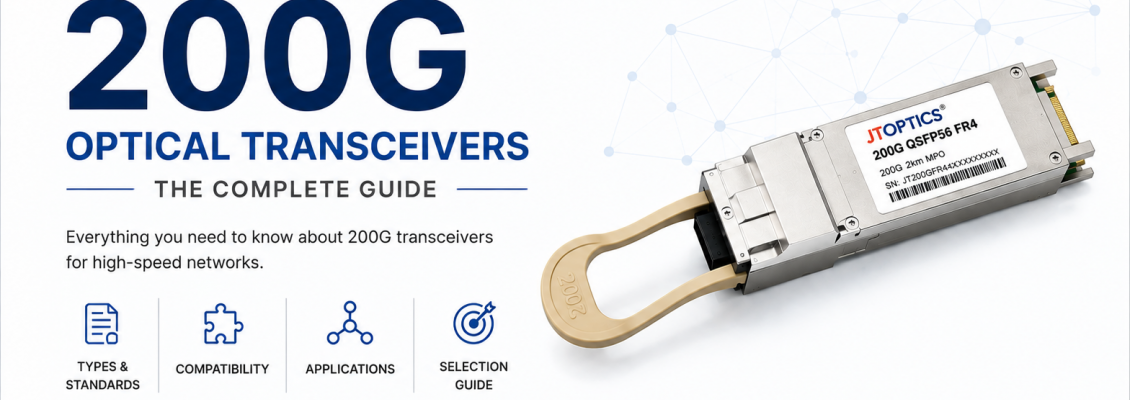
port, per rack unit, and per watt. The 200G optical transceiver
represents a key step in this progression, doubling per-port bandwidth relative
to 100G while introducing PAM4 modulation as a standard building block for
future speed grades.
This
guide is a companion to JT OPTICS' Complete Guide to 100G Optical Transceivers
and follows the same technical depth and structure, extending the discussion to
200G: its standards basis, internal architecture, module types, fiber and
connector compatibility, vendor interoperability, and a practical selection
framework for network engineers and procurement teams.
Why
200G Became Necessary?
The
jump from 100G to 200G was driven less by a single application and more by the
compounding effect of several workload categories growing simultaneously. AI
training clusters interconnect large numbers of GPUs that must exchange
gradient and parameter data with minimal latency; insufficient interconnect
bandwidth directly limits training throughput. Hyperscale cloud operators
continued expanding leaf-spine fabrics where east-west traffic between servers
routinely exceeds north-south traffic to the internet, making higher-radix,
higher-bandwidth switching essential. High performance computing clusters used
for scientific simulation and machine learning research have similar
interconnect demands to AI training environments. Storage systems built on NVMe
over Fabrics require throughput that keeps pace with increasingly fast
solid-state storage media. 5G transport networks, particularly midhaul and
backhaul segments aggregating multiple cell sites, require higher-capacity
links than 100G alone could economically provide at scale. Data center
interconnect (DCI) links between campus buildings or metro-distributed
facilities also benefit from higher per-fiber capacity as traffic volumes grow.
Rather
than simply doubling the number of 100G lanes, the industry adopted PAM4
(4-level pulse amplitude modulation) as the mechanism to increase per-lane
capacity, allowing 200G to be delivered over four electrical/optical lanes
instead of the eight lanes that would have been required using the older NRZ
modulation scheme at equivalent lane speeds. This kept module port density and
power consumption within practical bounds for dense switch platforms.
Evolution
of 200G Ethernet
IEEE
Standardization Path
Serial
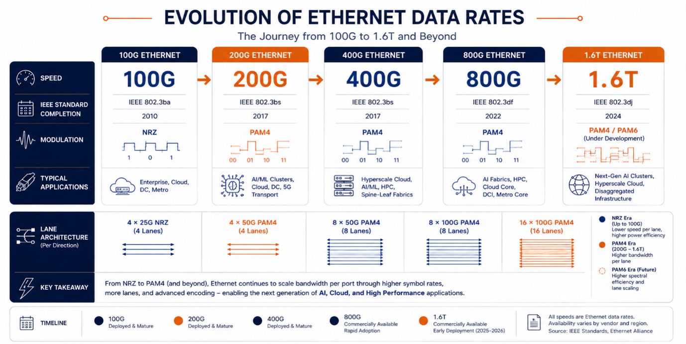
video and Ethernet Lane speeds have moved through successive generations, with
200G Ethernet formalized primarily under IEEE 802.3bs (originally
covering 200G and 400G Ethernet, ratified in 2017) and refined further under
IEEE 802.3cd, which defined 50 Gbps-per-lane PAM4 physical layer specifications
including 200GBASE-SR4, among others. These standards mark the formal transition
point where PAM4 became the default modulation format for new high-speed
Ethernet interfaces, superseding the NRZ (non-return-to-zero) modulation used
throughout the 10G, 40G, and 100G generations (except for some 100G single-lane
PAM4 variants that arrived later).
From
25G NRZ Lanes to 50G PAM4 Lanes
100G
Ethernet, in its most common QSFP28 implementation, is built from four lanes
each carrying 25.78125 Gbps using NRZ modulation. 200G Ethernet is built from
four lanes each carrying approximately 53.125 Gbaud using PAM4 modulation,
which encodes two bits per symbol rather than one, effectively doubling the
data rate carried per lane without doubling the baud rate to the same degree
that NRZ would have required. This lane architecture is often described using
the shorthand 4x50G PAM4, reflecting four logical 50 Gbps-class lanes.
Relationship
Between 100G, 200G, 400G, 800G, and 1.6T
These
successive Ethernet generations share a common lane-based building-block
philosophy. A single 50G PAM4 lane is the fundamental unit: four such lanes
produce 200G, eight lanes produce 400G, and further doublings using improved
SerDes generations (100G-per-lane PAM4) produce 800G and, more recently, 1.6T
interfaces. Because of this shared lineage, 200G QSFP56 ports are frequently
used as a breakout target for 400G QSFP-DD or OSFP ports, with a single 400G
port splitting into two 200G ports, or alternatively into four 100G ports,
depending on the breakout cable or module configuration selected.
What
Is a 200G Optical Transceiver?
A 200G
optical transceiver is a pluggable module that converts electrical signals from
a host switch, router, or server network interface card into modulated optical
signals for transmission over fiber, and performs the reverse conversion on the
receive path, at an aggregate data rate of 200 gigabits per second.
Working Principle
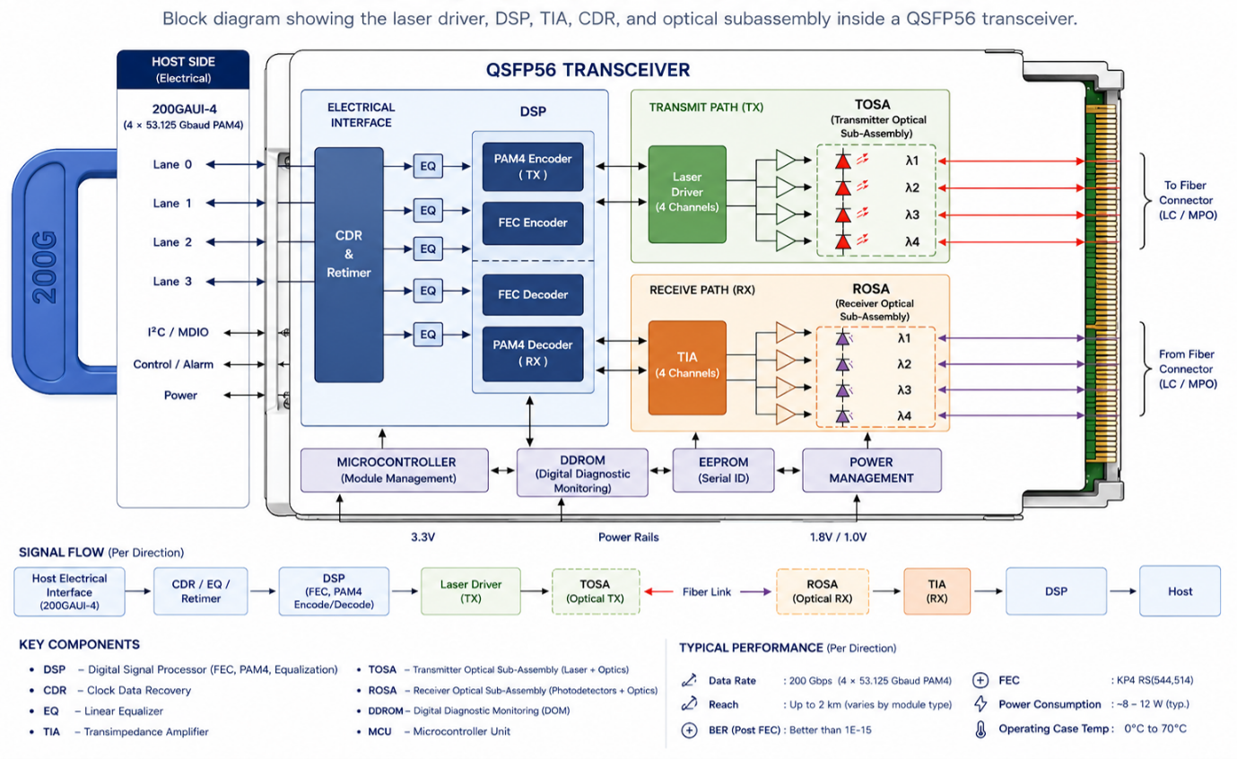
- Electrical
interface: The host side of a 200G transceiver
typically presents four electrical lanes, each operating at approximately
53.125 Gbaud using PAM4 signalling, consistent with the 200GAUI-4
electrical interface defined for this generation. Some earlier or
alternate implementations may use eight lanes of 25G PAM4 (200GAUI-8),
though four-lane 50G PAM4 electrical interfaces are the dominant
configuration in current QSFP56 modules.
- Optical engine:
The optical engine performs the core conversion between electrical and
optical domains. On transmit, a laser driver shapes the PAM4 electrical
waveform and drives a laser diode (VCSEL, DFB, or EML depending on the
module type) to produce a corresponding four-level modulated optical
signal. On receive, a photodetector converts incoming optical power into
an electrical current, which is amplified, equalized, and decoded back
into a PAM4 electrical waveform before being passed to the host.
- Signal flow and
DSP: Because PAM4 signalling has a smaller eye opening
between signal levels than NRZ, it is more sensitive to noise, dispersion,
and nonlinear impairments. Nearly all 200G modules therefore incorporate a
digital signal processor (DSP) performing equalization, forward error
correction (FEC) encoding and decoding, and clock recovery, functions that
are essential to achieving acceptable bit error rate (BER) performance
over the specified reach.
- Host interface and
optical interface: The host interface is defined by the
QSFP56 MSA's electrical pinout and signalling specification, while the
optical interface, wavelength plan, connector type, and reach vary by
module type as described in later sections.
Form
Factors
- QSFP56
QSFP56
(Quad Small Form-factor Pluggable, 56 Gbaud class) is the dominant form factor
for 200G optical transceivers. It shares the same mechanical footprint and host
cage as QSFP28, allowing switch vendors to reuse existing port and cage designs
while upgrading the electrical interface to support 50G PAM4 per lane. This
mechanical continuity has made QSFP56 a natural upgrade path for data centers
already using QSFP28-based 100G infrastructure.
- CFP2 and CFP2-DCO
CFP2
modules, part of the earlier C Form-factor Pluggable family, have also been
used for 200G and higher-rate interfaces, particularly in telecom and
metro/long-haul applications requiring more sophisticated optics than QSFP56's
compact power and space budget can accommodate. A notable variant, CFP2-DCO
(Digital Coherent Optics), integrates a coherent modem within the CFP2 form
factor, enabling long-haul and metro DWDM transport at 100G, 200G, or higher
per-wavelength rates. CFP2-DCO modules are primarily relevant to telecom
transport applications rather than intra-data-center Ethernet switching, and
they are mentioned here for completeness rather than as a typical data center
200G solution.
Comparison
with OSFP and QSFP-DD
OSFP
(Octal Small Form-factor Pluggable) and QSFP-DD (QSFP Double Density) are form
factors primarily associated with 400G and higher-speed interfaces, each
supporting eight electrical lanes rather than QSFP56's four. Both form factors
can host 200G optics as a breakout configuration, or QSFP-DD/OSFP 400G modules
can be split into two 200G logical ports depending on switch ASIC support. For
native 200G ports, QSFP56 remains the more common and power-efficient choice,
since it is purpose-built for four-lane 200G operation rather than being a
subset of an eight-lane 400G-capable design.
Advantages,
Limitations, Power, and Density
QSFP56's
principal advantage is high port density combined with a power envelope,
typically in the range of 4 to 6 watts for most 200G QSFP56 variants, that
remains manageable in high-density switch line cards. Its main limitation is
that being power- and space-constrained, it is generally suited to
direct-detect optical designs rather than coherent transmission, which
restricts its practical reach to the shorter and metro-scale distances covered
by SR4, FR4, LR4, and DR4 variants rather than long-haul telecom applications.
Internal
Architecture
The
internal architecture of a 200G transceiver builds on the same general
component set as 100G modules, with several elements upgraded or added to
support PAM4 signaling. The laser driver shapes the electrical drive current
for the laser diode according to the incoming PAM4 waveform, requiring more
precise linearity control than NRZ drivers due to PAM4's four discrete signal
levels. The PAM4 encoder, typically integrated within the DSP, maps electrical
bit streams into the four-level symbol structure required for PAM4
transmission. Forward error correction (FEC), most commonly a
Reed-Solomon-based scheme such as RS (544,514) as specified under IEEE
802.3bs/cd, adds redundancy that allows the receiver to correct a defined
proportion of transmission errors, which is essential given PAM4's reduced
noise margin relative to NRZ.
Laser
types of mirrors those used in 100G modules, selected according to reach and
module type: VCSELs for short-reach multimode designs such as SR4, DFB lasers
for cost-optimized single-mode designs, and EML (electro-absorption modulated
lasers) for longer-reach, higher-performance single-mode designs such as LR4
and higher-power FR4 variants. On the receive side, PIN photodiodes serve
shorter-reach, higher-power-budget links, while APDs (avalanche photodiodes)
provide the additional receiver sensitivity needed for longer-reach variants.
The
TIA (transimpedance amplifier) converts the photodiode's weak output current
into a usable voltage signal, which is further processed by an equalizer to
compensate for inter-symbol interference and channel-induced signal
degradation, a function that is considerably more demanding for PAM4 than for
NRZ due to the reduced spacing between signal levels. A retimer, often
integrated within the DSP, re-synchronizes the recovered signal to a clean
reference clock. CDR (clock and data recovery) circuitry performs the
underlying clock extraction function that the retimer and equalizer depend on.
An
onboard MCU manages module initialization and host communication, while the
EEPROM stores vendor identification, calibration, and operating parameter data.
Management of 200G and higher-speed modules increasingly relies on CMIS (Common
Management Interface Specification) rather than the older SFF-8636 standard
used for many 100G modules, since CMIS was designed to support the more complex
configuration and diagnostic requirements of PAM4-based, DSP-equipped optics.
Power
management circuitry regulates and distributes supply voltages across the laser
driver, DSP, TIA, and other active components. Thermal design, including an
integrated heat sink that conducts heat from the DSP and laser driver toward
the host cage, is more demanding in 200G modules than in 100G modules due to
the higher power dissipation of DSP-equipped PAM4 optics. The PCB routes
high-speed differential traces between the edge connector, which follows the
QSFP56 MSA's electrical pinout, and the optical engine, with careful attention
to controlled impedance and minimal crosstalk given the higher baud rates
involved.
200G
Module Types
200G
SR4 is standardized under IEEE 802.3cd as 200GBASE-SR4. It uses four parallel
optical lanes, each carrying approximately 53.125 Gbaud PAM4, transmitted over
multimode fiber with each lane on a separate fiber strand, similar in
architectural concept to 100GBASE-SR4 but at double the per-lane rate. The
nominal operating wavelength is 850 nm using VCSEL laser sources, and the
module uses an MPO-12 connector to accommodate the eight fibers required for
four transmit and four receive lanes.
Over
OM4 multimode fiber, 200GBASE-SR4 typically supports a maximum reach of
approximately 70 meters; over OM3, reach is reduced to approximately 30 meters,
reflecting OM4's higher modal bandwidth advantage becoming more pronounced at
higher per-lane baud rates. 200G SR4 is used for short intra-data-center links
such as top-of-rack to leaf-switch connections within the same or adjacent
racks, and its VCSEL-based design keeps cost and power consumption relatively
low compared to single-mode alternatives.
200G
FR4 is standardized under IEEE 802.3cd as 200GBASE-FR4. It multiplexes four
CWDM-style wavelengths, typically in the 1270–1330 nm range, onto a single
fiber pair using an LC duplex connector, with each wavelength carrying a
PAM4-modulated 53.125 Gbaud signal. FR4 uses EML laser sources for the transmit
path.
200GBASE-FR4
supports a maximum reach of approximately 2 kilometres over single-mode fiber,
making it well suited to data center interconnect applications, longer
intra-campus links, and connections between adjacent data halls or buildings
where duplex LC infrastructure is preferred over parallel MPO cabling. Because
it multiplexes all four lanes onto a single fiber pair, FR4 requires only two
fibers per 200G link, an efficiency advantage over parallel-fiber alternatives
such as SR4.
200G
LR4 is standardized under IEEE 802.3cd as 200GBASE-LR4, following the same
WDM-over-LC-duplex architectural approach as FR4 but engineered for longer
reach through higher-power EML lasers and more stringent optical budget
parameters. LR4 supports a maximum reach of approximately 10 kilometres over
single-mode fiber, positioning it for metro-scale connectivity, longer campus
links, and building-to-building links within larger data center campuses.
200G
DR4
200G
DR4 is standardized under IEEE 802.3bs as 200GBASE-DR4. Unlike SR4, FR4, and
LR4, which use four discrete optical lanes across separate fibers or
wavelengths, DR4 uses four separate single-wavelength optical lanes over four
individual single-mode fiber pairs (via an MPO-12 connector), each operating at
approximately 53.125 Gbaud PAM4 at a common wavelength near 1310 nm, without
wavelength multiplexing. DR4 supports a maximum reach of approximately 500
meters over single-mode fiber and is commonly used for point-to-point
single-mode links within a data center where reach beyond multimode SR4's range
is required but full WDM-based FR4/LR4 reach is unnecessary.
200G
Active Optical Cables (AOC) integrate the optical transceiver electronics
directly into each end of a fixed-length fiber cable assembly, rather than
being a separately pluggable module connected to user-supplied fiber. A 200G
AOC typically presents a QSFP56 electrical interface at each end, with an
internal VCSEL-based optical engine and multimode fiber running through the
cable jacket, supporting reach up to approximately 100 meters depending on the
specific design and fiber grade used. AOCs offer a lighter-weight, more
flexible alternative to both DAC (copper) and separately connectorized
transceiver-plus-fiber-patch-cord configurations, and they eliminate the need
for the installer to manage a separate fiber connection, since the fiber is
captive within the assembly.
200G
Direct Attach Copper (DAC) cables use twinax copper conductors with integrated
QSFP56 connectors at each end, providing a passive, low-cost, low-power
connectivity option for very short links, typically up to 2 to 3 meters, within
or between adjacent racks. Because DAC cables use direct electrical connections
rather than optical conversion, they consume no additional power beyond minimal
EEPROM/ID circuitry and introduce essentially no optical link budget
considerations, though their reach is inherently limited by copper signal
attenuation at high baud rates.
200G
Module Comparison Table
|
Module |
Standard |
Fiber
Type |
Wavelength |
Connector |
Lane
Architecture |
Max
Distance |
Typical
Use Case |
|
SR4 |
IEEE
802.3cd (200GBASE-SR4) |
Multimode
(OM3/OM4) |
~850
nm |
MPO-12 |
4x53G
PAM4 |
30–70
m |
Intra-rack,
ToR to leaf |
|
FR4 |
IEEE
802.3cd (200GBASE-FR4) |
Single
mode |
~1270–1330
nm CWDM |
LC
Duplex |
4-lambda
WDM PAM4 |
2 km |
Data
center interconnect |
|
LR4 |
IEEE
802.3cd (200GBASE-LR4) |
Single
mode |
~1270–1330
nm CWDM |
LC
Duplex |
4-lambda
WDM PAM4 |
10
km |
Campus/metro
links |
|
DR4 |
IEEE
802.3bs (200GBASE-DR4) |
Single
mode |
~1310
nm |
MPO-12 |
4x
single-wavelength PAM4 |
500
m |
Intra-data-center
point-to-point |
|
AOC |
QSFP56
MSA |
Multimode
(captive) |
~850
nm |
Captive
fiber, QSFP56 ends |
4x53G
PAM4 |
Up
to ~100 m |
Rack-to-rack,
flexible short links |
|
DAC |
QSFP56
MSA |
Twinax
copper |
N/A |
Captive
copper, QSFP56 ends |
4x53G
PAM4 electrical |
Up
to ~3 m |
Very
short, in-rack links |
Fiber
Compatibility
OM3
multimode fiber, with a modal bandwidth of approximately 2000 MHz·km at 850 nm,
supports 200GBASE-SR4 to a reduced reach of roughly 30 meters given the higher
per-lane baud rate compared to 100G. OM4, with approximately 4700 MHz·km modal bandwidths,
extends SR4 support to approximately 70 meters. OM5 wideband multimode fiber
offers similar modal bandwidth performance to OM4 at 850 nm with extended
performance across a broader wavelength range, relevant primarily to
short-wavelength-division-multiplexing (SWDM) applications rather than standard
SR4 deployments.
OS2
single-mode fiber, the standard choice for FR4, LR4, and DR4 modules, exhibits
very low attenuation, typically around 0.4 dB/km at 1310 nm, and negligible
modal dispersion, making it suitable for the multi-kilometer reaches these
modules target. Because 200G modules operate at higher baud rates and tighter
margins than their 100G counterparts, insertion loss and reflectance budgets
across connectors and splices become proportionally more significant, and
installers should pay close attention to insertion loss specifications
(typically 0.3 dB or better per mated connector pair for single-mode LC/MPO
interfaces) when designing 200G links close to a module's maximum rated
distance.
Fiber
Comparison Table
|
Fiber
Type |
Core
Diameter |
Modal
Bandwidth (850 nm) |
Typical
Attenuation |
200G
Use |
|
OM3 |
50
µm |
~2000
MHz·km |
~3.0
dB/km @850nm |
SR4
up to ~30 m |
|
OM4 |
50
µm |
~4700
MHz·km |
~3.0
dB/km @850nm |
SR4
up to ~70 m |
|
OM5 |
50
µm |
~4700
MHz·km (wideband) |
~3.0
dB/km @850nm |
SWDM,
emerging short reach |
|
OS2 |
9 µm |
N/A
(single mode) |
~0.4
dB/km @1310nm |
FR4/LR4/DR4 |
Connector
Compatibility
LC
duplex connectors are used by FR4 and LR4, since these modules multiplex all
four optical lanes onto a single fiber pair through CWDM wavelength
multiplexing. MPO-12 connectors are used by SR4 and DR4, since both require
eight or more discrete fiber strands (four transmit, four receive) without
wavelength multiplexing. Some higher-density breakout applications use MPO-16
connectors, particularly where 200G modules are configured for breakout into
multiple lower-rate ports requiring additional fiber positions. MTP connectors,
a trademarked, mechanically enhanced variant of MPO, are commonly used in
premium structured cabling systems for improved optical performance and
mechanical reliability.
Parallel
fiber cabling, as used by SR4 and DR4, requires careful polarity management
across trunk cables, patch panels, and breakout modules, governed by the same
Type A, Type B, and Type C polarity schemes used in 100G parallel-optics
deployments. Breakout cables, which split a single MPO-terminated 200G port
into multiple lower-rate LC-terminated ports (for example, 200G to 2x100G or
200G to 4x50G configurations), are widely used in hyperscale environments to
maximize switch port utilization when connecting to a mix of legacy and
current-generation server NICs.
Connector
Comparison Table
|
Connector |
Fiber
Count |
Used
By |
Polarity
Management |
|
LC
Duplex |
2 |
FR4,
LR4 |
No |
|
MPO-12 |
12
(8 used) |
SR4,
DR4 |
Yes
(Type A/B/C) |
|
MPO-16 |
16 |
Breakout/high-density
configurations |
Yes |
PAM4
Technology
Why
PAM4 Replaced NRZ
NRZ
modulation encodes one bit per symbol using two signal levels (high and low).
To double data rate under NRZ, the baud rate must also double, which becomes
increasingly difficult and costly at high frequencies due to channel loss,
component bandwidth limitations, and electromagnetic interference
considerations. PAM4 instead encodes two bits per symbol using four distinct
signal levels, allowing data rate to double relative to NRZ at the same baud
rate. This made PAM4 the practical choice for reaching 50 Gbps-class and 100
Gbps-class per-lane rates without requiring baud rates that would be
impractical to support reliably over standard channel materials and connector
interfaces.
Signal
Levels, Eye Diagrams, and BER
A PAM4
signal uses four amplitude levels to represent the symbol pairs 00, 01, 10, and
11. Because the vertical spacing between adjacent signal levels is roughly
one-third that of an equivalent-swing NRZ signal, PAM4 has inherently less
noise margin between levels, which is visually represented by three smaller
"eye openings" in a PAM4 eye diagram compared to the single larger
eye of an NRZ signal. This reduced margin means that a given level of channel
noise or distortion produces a higher raw bit error rate (BER) under PAM4 than
it would under NRZ, which is why strong forward error correction is treated as
a mandatory, integral part of PAM4-based interfaces rather than an optional
enhancement.
Advantages
and Challenges
The
principal advantage of PAM4 is doubled spectral efficiency, enabling higher
data rates without proportionally higher baud rates, which helps contain the
cost and complexity of components such as connectors, PCB traces, and
driver/receiver ICs. The principal challenges are reduced noise margin, greater
sensitivity to nonlinearities and reflections, and a corresponding dependency
on DSP-based equalization and FEC to achieve acceptable link performance, all
of which increase the complexity, power consumption, and cost of PAM4-based
transceivers relative to comparable-generation NRZ designs.
DSP
and FEC
The
DSP in a PAM4-based transceiver performs several tightly coupled functions:
adaptive equalization to compensate for frequency-dependent channel loss and
reflections, PAM4 symbol detection and decoding, and coordination with the FEC
decoder to correct residual errors. FEC schemes such as RS (544,514), specified
for many IEEE 802.3cd interfaces, add a defined amount of redundant data that
allows the receiver to detect and correct a bounded number of symbol errors per
codeword, which is what allows PAM4-based links to achieve the same effective
error rate performance that end applications require, despite PAM4's higher raw
BER prior to correction.
PAM4
vs NRZ Comparison Table
|
Characteristic |
NRZ |
PAM4 |
|
Signal
levels |
2 |
4 |
|
Bits
per symbol |
1 |
2 |
|
Relative
noise margin |
Higher |
Lower
(~1/3 of NRZ per level) |
|
Baud
rate for equivalent data rate |
Higher |
Lower |
|
FEC
dependency |
Optional
in some designs |
Effectively
mandatory |
|
Typical
generation |
10G–100G
(4x25G) |
50G-class
lanes and above |
Vendor
Compatibility
200G
QSFP56 optics are supported across major switching and routing platforms from
Cisco, Arista, Juniper, Dell, NVIDIA, Huawei, HPE, Extreme, and MikroTik, among
others, since the QSFP56 MSA and underlying IEEE 802.3cd/bs optical standards
are vendor-neutral specifications. As with 100G optics, many OEM switch
platforms implement a vendor identification check by reading data stored in the
transceiver's EEPROM against an approved vendor list, a practice generally
referred to as vendor locking.
Third-party
transceiver suppliers, including JT OPTICS, address this through OEM coding,
meaning EEPROM programming that matches the vendor identification format
expected by a specific switch platform, allowing the module to pass host
validation without altering the underlying optical or electrical specifications
governed by the applicable IEEE or MSA standard. Because 200G modules are more
complex, DSP-equipped, CMIS-managed devices compared to earlier-generation
optics, compatibility testing across the specific switch platform, firmware
version, and CMIS revision supported is particularly important, and network
engineers should confirm compatibility documentation with their transceiver
supplier before large-scale deployment.
Applications
200G
optical transceivers serve a similar application landscape to 100G optics,
shifted toward higher bandwidth use cases. In enterprise networks, 200G is
increasingly used for core and aggregation uplinks in larger environments. In
cloud and hyperscale data centers, 200G serves as a leaf-spine fabric speed in
newer deployments, and as a breakout target for 400G spine links. AI and
machine learning clusters use 200G (and increasingly 400G/800G) for GPU
interconnect and storage fabric traffic, where interconnect bandwidth directly
affects training throughput. Storage systems adopting NVMe over Fabrics benefit
from 200G's higher per-port throughput. 5G networks use 200G for midhaul and
backhaul aggregation where traffic volumes exceed what 100G links can
economically support. Telecom, campus, and metro networks use 200G FR4 and LR4
for longer-reach interconnects, while data center interconnect (DCI)
applications commonly rely on FR4 for building-to-building or campus-scale
links. High performance computing, financial networks, government, and
healthcare organizations adopt 200G where their respective workloads, trading
infrastructure, secure data replication, or large imaging datasets, require
higher sustained throughput than 100G can provide.
Selection
Guide: Choosing the Right 200G Module
- Distance
is the primary starting point: links under roughly 70 meters over existing
multimode fiber favor SR4; single-mode links up to 500 meters favor DR4;
links up to 2 kilometres favor FR4; and links up to 10 kilometres require
LR4.
- Fiber type
already installed in a facility often narrows the decision quickly. Sites
with only multimode fiber favor SR4 to avoid a fiber plant upgrade; sites
with single-mode fiber, or new construction, have the flexibility to
select DR4, FR4, or LR4 based on distance requirements.
- Connector
infrastructure should be assessed alongside fiber type, since MPO-based
modules (SR4, DR4) require different patch panel and trunk cable
infrastructure than LC-duplex-based modules (FR4, LR4).
- Budget
considerations typically favor SR4 and DAC for the shortest links, AOC for
flexible short-to-medium reach without fiber plant investment, and FR4/LR4
for longer single-mode links where their higher per-unit cost is offset by
the efficiency of a single fiber pair.
- Switch
compatibility must be verified against the specific
platform, firmware version, and CMIS revision supported, along with
confirmation of vendor coding requirements where applicable.
- Future scalability
favors modules and cabling infrastructure that align with anticipated
migration to 400G, since MPO-based parallel infrastructure and DR-family
single-wavelength architectures share more structural continuity with
higher-speed breakout configurations than legacy WDM approaches.
- Power
budgets should be checked against the switch's per-port power allowance,
since 200G DSP-equipped modules generally draw more power than comparable
100G optics; this is particularly relevant in very high-density line
cards.
- Temperature and
deployment environment considerations mirror those for 100G
optics: standard commercial-temperature modules (0°C to 70°C) may be
insufficient for outdoor cabinets or extreme environments, which instead
require industrial or extended-temperature-rated modules.
Practical
Deployment Notes and Best Practices
A
typical AI training cluster or hyperscale leaf-spine deployment might use 200G
SR4 or DR4 modules for server-to-leaf connections within a rack row, while
using 200G FR4 modules for leaf-to-spine links traversing longer distances
across a data hall on single-mode fiber, or as breakout components of 400G
spine uplinks. A metro-scale interconnect between two nearby facilities might
deploy 200GBASE-LR4 over dedicated single-mode fiber, taking advantage of its
10-kilometer IEEE-standardized reach.
Because
PAM4-based 200G links operate with tighter margins than NRZ-based 100G links,
best practices include verifying end-to-end optical loss budgets with
additional care, particularly for FR4 and LR4 deployments approaching maximum
rated distance; maintaining strict fiber connector cleanliness, since
contamination has a proportionally larger impact on PAM4 link margin than on
NRZ; monitoring DDM/CMIS telemetry data continuously to catch early signs of
module degradation; and confirming CMIS revision compatibility between
transceiver and host platform before deployment, since mismatched CMIS support
can cause management or monitoring issues even when the underlying optical link
functions correctly.
Common
mistakes include applying 100G-era optical loss budget assumptions to 200G
links without accounting for PAM4's reduced margin, deploying SR4 over OM3
fiber at distances exceeding its reduced ~30-meter reach, mismatching MPO
connector polarity across parallel-fiber links, and failing to verify CMIS and
firmware compatibility between transceiver and switch before large-scale
rollout.
Cost
and Standards Considerations
As
with 100G optics, a general cost hierarchy exists across 200G module types,
typically increasing from DAC as the lowest-cost, shortest-reach option,
through AOC and SR4, to DR4, and finally to FR4 and LR4 as the higher-cost,
longer-reach options, reflecting the increasing sophistication of laser
technology and, for FR4/LR4, WDM multiplexing components.
It is
worth distinguishing IEEE-standardized interfaces from MSA-governed
specifications when evaluating 200G modules for procurement. 200GBASE-SR4, FR4,
LR4, and DR4 are all formally defined under IEEE 802.3cd or 802.3bs, subject to
the IEEE's standards development and interoperability testing processes. The
QSFP56 mechanical and electrical form factor itself, by contrast, is governed
by the QSFP-DD MSA group's QSFP56 specification (a multi-source industry
agreement) rather than by IEEE, meaning the physical module footprint and pin
assignment follow MSA governance while the optical interface specifications
follow IEEE governance, a division of responsibility consistent with how QSFP28
and 100G Ethernet standards are structured.
Standards
Comparison Table
|
Standard
Body |
Module
Examples |
Governance |
|
IEEE
802.3cd / 802.3bs |
SR4,
FR4, LR4, DR4 |
Formal
international standards body |
|
QSFP-DD
MSA (QSFP56 spec) |
QSFP56
mechanical/electrical form factor |
Industry
consortium specification |
|
CMIS |
Module
management interface |
OIF-aligned
multi-source specification |
JTOPTICS® 200G Solutions:
JTOPTICS® provides a broad portfolio of optical
connectivity products spanning both the 100G and 200G Ethernet generations,
including 200G QSFP56 optical transceivers across SR4, FR4, LR4, and DR4
variants, 200G DAC and AOC cables, MPO/MTP cabling assemblies, fiber patch
cords, and broader data center connectivity solutions. Network engineers and
procurement teams evaluating 200G connectivity can apply the same technical
framework outlined in this guide, distance, fiber type, connector
infrastructure, switch and CMIS compatibility, power budget, and future
scalability, to identify the module type best suited to their specific
deployment, using this article alongside JT OPTICS' Complete Guide to 100G
Optical Transceivers as part of a unified technical reference for optical
connectivity planning.
Frequently
Asked Questions
1.
What is the difference between 200G QSFP56 and 100G QSFP28?
QSFP56 and QSFP28 share the same mechanical footprint, but QSFP56 supports four
lanes of approximately 53G PAM4 signalling, while QSFP28 supports four lanes of
25G NRZ signalling, giving QSFP56 double the aggregate data rate.
2. Can
a QSFP56 module be used in a QSFP28 port? No. Although the
mechanical form factor is compatible, the switch ASIC and port must explicitly
support 200G QSFP56 electrical signalling and PAM4 decoding.
3. Why
does 200G use PAM4 instead of NRZ? PAM4 encodes two bits per
symbol instead of one, allowing data rate to double without a corresponding
doubling of baud rate, which keeps component and channel design more practical
at high speeds.
4.
What is the maximum reach of 200GBASE-SR4? 200GBASE-SR4 typically
supports up to approximately 70 meters over OM4 multimode fiber and
approximately 30 meters over OM3.
5.
What connector does 200GBASE-FR4 use? 200GBASE-FR4 uses an LC
duplex connector, since all four wavelengths are multiplexed onto a single fiber
pair.
6.
What is the difference between 200GBASE-FR4 and 200GBASE-LR4? Both
use four CWDM wavelengths over a single fiber pair, but LR4 is engineered for
up to approximately 10 kilometres of reach using higher-power EML lasers, while
FR4 targets a shorter 2-kilometer reach.
7. Is
200GBASE-DR4 single-mode or multimode? 200GBASE-DR4 uses single-mode
fiber, with four separate single-wavelength lanes over an MPO-12 connector
rather than wavelength multiplexing.
8. Why
is FEC considered mandatory for PAM4-based interfaces?
PAM4's four-level signalling has less noise margin than NRZ's two-level
signalling, resulting in a higher raw bit error rate that FEC must correct to
achieve acceptable end-to-end link performance.
9.
What is CMIS and why does it matter for 200G modules? CMIS
(Common Management Interface Specification) is a management interface standard
designed to support the more complex configuration and diagnostic needs of
DSP-equipped, PAM4-based optics, and is increasingly used in place of the older
SFF-8636 standard for 200G and higher-speed modules.
10.
What is the typical power consumption of a 200G QSFP56 module?
Typical power consumption ranges from approximately 4 to 7 watts depending on
module type, with SR4 generally at the lower end and LR4 at the higher end of
that range.
11.
Can 200G ports be used as a breakout from 400G switch ports? Yes,
many 400G QSFP-DD or OSFP switch ports support breakout into two 200G ports,
depending on the switch ASIC and the specific breakout cable or module used.
12.
What fiber is required for 200GBASE-LR4? 200GBASE-LR4 requires
single-mode fiber (OS2), supporting reach up to approximately 10 kilometres.
13. Do
all 200G modules use four electrical lanes? Most current QSFP56
modules use a four-lane 200GAUI-4 electrical interface at approximately 53G
PAM4 per lane; some earlier or alternate designs used an eight-lane 200GAUI-8
interface at 25G PAM4 per lane.
14.
What is the difference between AOC and DAC for 200G links? AOC
(Active Optical Cable) uses captive optical transceivers and fiber within the
cable assembly, supporting reach up to roughly 100 meters, while DAC (Direct
Attach Copper) uses passive twinax copper conductors, limited to a few meters
of reach but with no additional power consumption.
15.
Why do some switches reject third-party 200G transceivers? Many
switch vendors implement a vendor identification check against data stored in
the transceiver's EEPROM; third-party modules not coded to match an approved
vendor list may trigger warnings or, in some configurations, be disabled.
16.
Does OEM EEPROM coding affect the optical performance of a 200G module? No.
Compatibility coding only modifies identification data read by the host
platform during initialization; it does not alter the underlying optical or
electrical specifications governed by the applicable IEEE or MSA standard.
17.
What is the difference between QSFP56 and QSFP-DD?
QSFP56 supports four electrical lanes and is purpose-built for native 200G
operation, while QSFP-DD supports eight electrical lanes and is purpose-built
for native 400G operation, with breakout support down to 200G or 100G depending
on configuration.
18.
What is the role of an equalizer in a 200G receiver? The
equalizer compensates for inter-symbol interference and channel-induced signal
degradation, which is more demanding under PAM4 than NRZ due to PAM4's reduced
spacing between signal levels.
19.
What laser type is typically used in 200GBASE-LR4?
200GBASE-LR4 typically uses EML (electro-absorption modulated laser) sources,
selected for their combination of high modulation speed and low chirp suited to
longer-reach single-mode transmission.
20. Is
OM3 fiber suitable for 200GBASE-SR4 at distances beyond 30 meters? No.
OM3's modal bandwidth limits 200GBASE-SR4 reach to approximately 30 meters;
exceeding this distance risks unreliable link performance due to insufficient
optical budget margin.