




The
transition from 10 Gigabit and 40 Gigabit Ethernet to 100 Gigabit Ethernet
represents one of the most significant inflection points in the history of data
center and telecommunications networking. As
traffic volumes generated by cloud services, artificial intelligence workloads,
video streaming, and mobile broadband continue to climb, the underlying
physical layer infrastructure has had to keep pace. The 100G
Optical Transceiver sits at the center of this transformation,
converting electrical signals into modulated light and back again across
single-mode and multimode fiber links that connect switches, routers, and
servers.
This
blog provides a comprehensive technical examination of 100G optical
transceivers, including their internal architecture, the IEEE and multi-source
agreement (MSA) standards that define them, the various module types available
on the market, fiber and connector compatibility, vendor interoperability
considerations, and a practical framework for selecting the correct module for
a given network design. The intent is to serve as a lasting technical reference
for network engineers, data center architects, and procurement professionals
who need to make informed decisions about 100G optical connectivity.
Ethernet
has evolved through successive generations, each driven by a specific set of
bandwidth pressures. The IEEE 802.3ba amendment, ratified in 2010, was the
first standard to define both 40 Gigabit Ethernet (40GbE) and 100 Gigabit
Ethernet (100GbE) simultaneously, targeting server aggregation and core network
links respectively. At the time, 100GbE was implemented using large,
power-hungry CFP modules intended primarily for long-haul telecom and core
routing applications.
The
real acceleration of 100G adoption in data centers occurred later in the
decade, driven by several converging trends. Cloud computing providers began
deploying hyperscale data centers with tens of thousands of servers, requiring
leaf-spine fabric architectures that demanded dense, low-power, high-radix
switching. The rise of virtualization and software-defined networking increased
east-west traffic within data centers far beyond traditional north-south
client-server patterns. Machine learning and high-performance computing (HPC)
clusters introduced new demands for low-latency, high-bandwidth interconnects
between compute nodes. The commercial rollout of 5G networks required higher
capacity backhaul and fronthaul links between cell sites and aggregation
points. Storage area networks transitioning to Ethernet-based fabrics (such as
NVMe over Fabrics) also needed higher throughput per port.
These
pressures collectively pushed the industry toward smaller, denser, and more
power-efficient optical modules. The QSFP28 form factor emerged as the
practical answer, enabling 100G to be delivered in a footprint compatible with
existing QSFP cage designs, at a fraction of the power consumption of
first-generation CFP modules. This shift is what ultimately allowed 100G
Ethernet to move from a niche core-networking technology into the default
access and aggregation speed across enterprise and hyperscale data centers
alike.
Understanding
100G Optical Transceivers
What is a 100G Optical Transceiver?
A
100G optical transceiver is a pluggable module that provides bidirectional
conversion between electrical signals inside networking equipment and optical
signals carried over fiber optic cabling, operating at an aggregate data rate
of 100 gigabits per second. The transceiver plugs into a cage and connector on
a switch, router, or server network interface card, and it interfaces with the
host system's electrical serializer/deserializer (SerDes) lanes on one side
while presenting an optical fiber interface on the other.
The
transceiver's function can be separated into two directions of signal flow. On
the transmit path, the module accepts electrical data from the host, conditions
and retimes the signal, drives a laser diode to modulate light according to the
incoming data pattern, and couples that modulated light into the fiber. On the
receive path, the module detects incoming light using a photodiode, converts it
back into an electrical current, amplifies and reshapes that signal, and
delivers clean electrical data to the host's receiver circuitry.
Working Principle: Electrical to Optical Conversion
On
the transmit side, incoming electrical data arrives from the host system across
one or more SerDes lanes, commonly at 25 Gbps or 50 Gbps per lane depending on
the module generation. This electrical signal passes through a laser driver
integrated circuit, which converts the digital electrical waveform into a
modulated drive current suitable for a laser diode. Depending on the module
type, the laser may be a vertical-cavity surface-emitting laser (VCSEL), a
distributed feedback (DFB) laser, or an electro-absorption modulated laser
(EML). The laser converts the electrical drive current into modulated optical
power, and that optical signal is coupled into the fiber core through precision
optical alignment components within the transceiver housing.
Working Principle: Optical to Electrical Conversion
On
the receive side, incoming optical signals from the fiber strike a
photodetector, typically a PIN photodiode or, for longer-reach applications
requiring greater sensitivity, an avalanche photodiode (APD). The photodetector
converts optical power into a small electrical current proportional to the
received light intensity. Because this current is extremely weak, it is
immediately amplified by a transimpedance amplifier (TIA), which converts the
current into a usable voltage signal and provides initial gain. The signal is
then further conditioned by a limiting amplifier and passed through clock and
data recovery (CDR) circuitry, which re-synchronizes the data to a clean clock
reference before delivering it to the host electrical interface.
Host Interface and Optical Interface
The
host interface defines how the transceiver communicates electrically with the
switch or router ASIC. For 100G modules, this is most commonly implemented as
four lanes of 25 Gbps electrical signaling (4x25G NRZ) in earlier-generation
modules, though newer designs may use different lane configurations such as
2x50G PAM4 depending on the host SerDes generation. The optical interface, by
contrast, defines the physical fiber connector, the number of optical lanes or
wavelengths, the modulation format, and the operating wavelength range, all of
which vary by module type as described in later sections.
Signal Processing and DSP
Many
100G transceivers, particularly those supporting longer reach applications or
PAM4 modulation, incorporate a digital signal processor (DSP) that performs
functions such as forward error correction (FEC) encoding and decoding,
equalization to compensate for chromatic dispersion and inter-symbol
interference, and clock recovery. Simpler, shorter-reach modules such as 100G
SR4 may rely on direct-detect architectures without a full DSP, using simpler
retiming circuitry instead, which helps keep power consumption and latency
lower for intra-data-center links.
QSFP28 Form Factor
QSFP28 (Quad Small Form-factor
Pluggable 28) is the dominant form factor for 100G optical transceivers. It is
mechanically similar to the earlier QSFP+ form factor used for 40G modules,
sharing the same footprint and latching mechanism, but it incorporates upgraded
electrical lanes capable of supporting 25 Gbps per lane across four lanes,
hence the "28" designation referring to the per-lane signaling rate
class. This backward-compatible mechanical footprint was a major factor in
QSFP28's rapid adoption, since switch vendors could reuse existing cage designs
and port densities while upgrading from 40G to 100G.
CFP, CFP2, and CFP4
Before
QSFP28 became dominant, 100G Ethernet was primarily delivered through the C
Form-factor Pluggable (CFP) family of modules, defined by the CFP MSA. CFP
modules were substantially larger than QSFP28, originally designed to support a
single 100G port using 10x10G electrical lanes, and were primarily deployed in
long-haul telecom and core router applications where port density was less
critical than optical performance and reach.
CFP2
reduced the physical size roughly in half relative to the original CFP,
allowing higher port density per line card while retaining support for coherent
and long-reach optical interfaces. CFP4 further reduced the form factor,
approaching a size closer to QSFP form factors, and was used in some data
center core applications, though it did not achieve the same level of market
penetration as QSFP28.
Differences and Trade-offs
The
essential trade-off between CFP-family modules and QSFP28 is one of density
versus optical sophistication. CFP and CFP2 modules can accommodate more
complex optics, higher power dissipation budgets, and in some designs support
for tunable or coherent optical interfaces used in metro and long-haul DWDM
systems. QSFP28's compact size imposes a stricter power budget, generally in
the range of 3.5 to 4.5 watts for most standard 100G QSFP28 variants, which
constrains the module to simpler direct-detect optical designs for the majority
of use cases.
Why QSFP28 Became Dominant
QSFP28
became the dominant 100G form factor in data center networking because it
allowed switch vendors to deliver very high port density, often 32 or more 100G
ports in a single 1U switch, while maintaining power consumption low enough for
practical thermal management at scale. The shared mechanical heritage with
QSFP+ also meant that data center operators transitioning from 40G to 100G
could largely reuse existing cabling infrastructure and cage designs, easing
the migration path. As hyperscale and enterprise data centers represent the
largest volume consumers of 100G optics, QSFP28's fit for that use case made it
the de facto standard, even though CFP-family modules retain relevance in
certain telecom core and long-haul applications.
Internal
Architecture of a 100G Transceiver
The internal architecture of a 100G
optical transceiver integrates a number of specialized components on a compact
printed circuit board (PCB), all housed within a metal shell that also serves
as a heat sink and EMI shield.
The
laser driver is the integrated circuit responsible for converting incoming
electrical data into a precisely controlled current waveform that drives the
laser diode, shaping rise and fall times and bias current to achieve the
required extinction ratio and eye quality. Depending on the module type, the
laser itself may be a VCSEL, typically used in short-reach multimode designs
such as SR4 due to its low cost and low power consumption; a DFB laser, used in
single-mode long-reach designs for its narrow spectral linewidth and wavelength
stability; or an EML, which combines a DFB laser with an integrated
electro-absorption modulator to achieve higher-speed, lower-chirp modulation
suited to longer-reach single-mode links such as LR4 and ER4.
On the receive side, a PIN photodiode is commonly used for shorter-reach applications where received optical power is relatively high, while an APD (avalanche photodiode) provides internal gain and greater sensitivity, making it suitable for longer-reach or lower-power-budget links such as ER4. The TIA (transimpedance amplifier) converts the photodiode's weak current output into a voltage signal with sufficient gain for further processing, and a limiting amplifier further shapes this signal to a consistent output amplitude regardless of input signal strength variation.
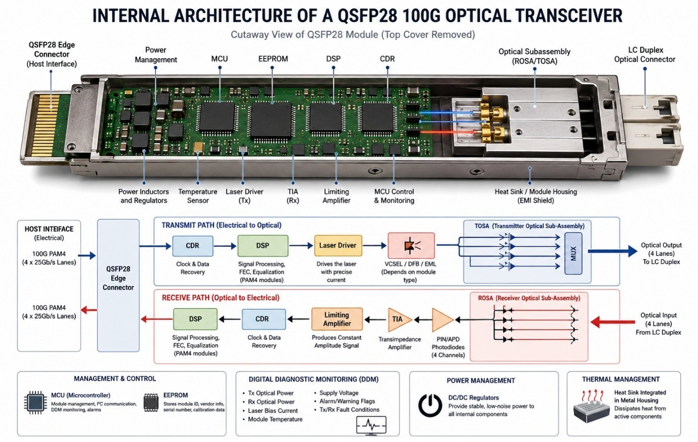
Clock
and data recovery (CDR) circuitry extracts a clean, synchronized clock from the
incoming data stream and retimes the data accordingly, removing jitter
accumulated during optical transmission. In more sophisticated modules, a DSP
(digital signal processor) performs equalization, forward error correction, and
additional signal conditioning, particularly important in PAM4-based or
extended-reach designs.
An
onboard EEPROM stores the module's identification data, vendor information,
serial number, supported operating parameters, and, in many cases, digital
diagnostic monitoring calibration data, conforming to standards such as
SFF-8636 or the newer CMIS (Common Management Interface Specification). A microcontroller
(MCU) manages module initialization, communicates with the host over the I2C
management interface, and implements Digital Diagnostic Monitoring (DDM), which
continuously reports parameters such as transmit and receive optical power,
laser bias current, module temperature, and supply voltage, allowing network
operators to proactively monitor link health.
Thermal
management is handled through a metal heat sink integrated into the module
housing, which conducts heat away from the laser driver, DSP, and other active
components toward the host cage, where airflow dissipates it. The electrical
connector, typically an edge connector compliant with the QSFP28 MSA, provides
the physical and electrical interface to the host cage. Internally, a compact
multilayer PCB routes high-speed differential electrical traces between the
edge connector and the optical engine while minimizing signal loss and
crosstalk. A dedicated power management subsystem regulates and distributes the
module's supply voltages to each active component, ensuring stable operation
across the specified temperature range.
Types
of 100G Optical Modules
The
100G Ethernet ecosystem includes several distinct optical module types, each
defined by a specific IEEE and/or MSA standard, engineered for a particular
reach, fiber type, and application profile. The most common types are SR4,
PSM4, CWDM4, LR4, ER4, DR, and FR.
100G SR4 (Short Reach 4) is defined under IEEE 802.3ba as the 100GBASE-SR4 physical layer specification. It uses four parallel optical lanes, each operating at 25 Gbps using NRZ modulation, over multimode fiber, with each lane transmitted and received on a separate fiber strand rather than being wavelength-multiplexed. The nominal operating wavelength is around 850 nm, using VCSEL laser sources, which are inexpensive and well suited to short multimode links. The module uses an MPO-12 connector to accommodate the eight fibers required (four transmit, four receive).
Over
OM4 multimode fiber, 100GBASE-SR4 supports a maximum reach of approximately 100
meters; over OM3, the supported reach is reduced to approximately 70 meters due
to OM3's lower modal bandwidth. 100G SR4 is widely used for short
intra-data-center links, such as top-of-rack to leaf-switch connections and
short server-to-switch links within the same or adjacent racks.
The
primary advantage of SR4 is its low cost and low power consumption relative to
single-mode alternatives, since VCSELs and multimode fiber optics are
inherently less expensive than DFB/EML-based single-mode designs. Its principal
disadvantage is limited reach, making it unsuitable for building-to-building or
metro-scale links. Typical customers include hyperscale and enterprise data center
operators building leaf-spine fabrics with short cable runs, and it is broadly
compatible with switches from Cisco, Arista, Juniper, Dell, and other major
vendors that support standard QSFP28 SR4 optics.
100G PSM4
100G PSM4 (Parallel Single Mode 4) is defined by the PSM4 MSA rather than an IEEE standard. Like SR4, it uses four parallel optical lanes, each at 25 Gbps NRZ, but over single-mode fiber rather than multimode, and typically uses DFB or similar single-mode laser sources operating near 1310 nm. PSM4 also uses an MPO-12 connector, with eight single-mode fibers total.
PSM4
supports a maximum reach of approximately 500 meters over single-mode fiber,
positioning it between SR4's short multimode reach and the longer
wavelength-division-multiplexed options. It is commonly deployed in hyperscale
data centers for longer intra-campus links where multimode fiber's distance
limitations are insufficient, but full CWDM4/LR4 reach is not required. Because
PSM4 uses parallel fiber pairs rather than wavelength multiplexing, it requires
more fiber strands per link than CWDM4 or LR4, which is a consideration in
fiber-constrained environments. PSM4 has seen substantial adoption among
hyperscale cloud operators due to its relatively lower cost per port compared
to WDM-based single-mode alternatives.
100G CWDM4
100G
CWDM4 (Coarse Wavelength Division Multiplexing 4) is defined by the CWDM4 MSA.
It multiplexes four optical lanes, each at 25 Gbps, onto four distinct CWDM
wavelengths within the 1310 nm window, combining them onto a single fiber pair
(one for transmit, one for receive) using an optical multiplexer and
demultiplexer inside the module. This design uses a standard LC duplex
connector rather than an MPO connector, since only two fibers are needed.
CWDM4
supports a maximum reach of approximately 2 kilometers over single-mode fiber.
It is well suited to data center interconnect (DCI) applications and longer
intra-campus links where duplex LC fiber infrastructure is preferred over
parallel MPO cabling. A key advantage of CWDM4 is its efficient use of fiber,
since it requires only a single fiber pair per 100G link, in contrast to the
eight fibers required by SR4 or PSM4. Its primary disadvantage relative to
those parallel options is a somewhat higher cost due to the WDM optical
components required.
100G
LR4
100G
LR4 (Long Reach 4) is standardized under IEEE 802.3ba as 100GBASE-LR4. Similar
in principle to CWDM4, it multiplexes four wavelengths in the 1310 nm range
onto a single fiber pair, but uses EML lasers rather than simpler DFB sources
to achieve better performance over longer distances, and it is engineered to a
stricter set of optical budget parameters defined by IEEE. LR4 uses an LC
duplex connector.
100GBASE-LR4
supports a maximum reach of 10 kilometers over single-mode fiber (OS1/OS2),
making it suitable for longer campus links, metro connectivity, and
building-to-building links within a large data center campus. Because it is an
IEEE-standardized interface, LR4 benefits from broad multi-vendor
interoperability testing and is widely regarded as a highly reliable choice for
links requiring guaranteed standards compliance. Its main disadvantage compared
to CWDM4 is higher cost, driven by the more sophisticated EML laser technology
and tighter optical specifications required to meet the IEEE reach target.
100G
ER4
100G
ER4 (Extended Reach 4) is standardized under IEEE 802.3bm as 100GBASE-ER4, also
using four CWDM-style wavelengths in the 1310 nm range over a single LC duplex
fiber pair, but engineered for substantially longer reach through the use of
higher-power EML lasers and, in the receive path, avalanche photodiodes for
improved sensitivity. Some ER4 implementations also include an optical
amplifier stage to boost transmit power further.
100GBASE-ER4
supports a maximum reach of approximately 40 kilometers over single-mode fiber,
positioning it for metro network applications, long-haul data center
interconnect, and telecom aggregation links. ER4 modules typically consume more
power than LR4 due to the additional amplification and higher-performance
receiver components, and they carry a correspondingly higher cost. They are
primarily deployed by telecommunications carriers, large enterprises with
metro-scale connectivity requirements, and ISPs linking geographically
distributed facilities.
100G DR
100G DR is defined under IEEE 802.3bs/cd as 100GBASE-DR, representing a newer generation of single-mode optics designed around a single-wavelength, single-lane 100 Gbps electrical/optical signal path (using PAM4 modulation on the host side in many implementations) rather than four parallel 25G lanes. It uses a single-mode fiber pair with an LC duplex connector and operates in the 1310 nm window.
100GBASE-DR
supports a maximum reach of 500 meters over single-mode fiber. It was developed
in the context of next-generation 400G/800G module architectures, where a
single 100G-per-lane building block (using 4-level pulse amplitude modulation,
PAM4) is reused across breakout configurations. DR modules are commonly used in
newer hyperscale data center designs migrating toward higher aggregate switch
bandwidths, where 100G DR ports may also be used as a breakout of a 400G port.
100G FR
100G
FR (Fast Reach) is standardized under IEEE 802.3cn as 100GBASE-FR, closely
related to DR in its single-wavelength, single-lane PAM4-based architecture,
but engineered for greater reach. It uses a single-mode fiber pair with an LC
duplex connector at 1310 nm.
100GBASE-FR supports a maximum reach of 2 kilometers over single-mode fiber, making it a modern alternative to CWDM4 for similar distance requirements, but built on newer single-lane PAM4 technology that aligns more directly with the electrical architecture used in contemporary 400G and 800G systems. As switch platforms increasingly adopt higher-speed SerDes lanes, FR and DR are gaining adoption as more forward-compatible choices for new deployments, since their electrical design shares a common lineage with higher-speed breakout modules.
100G Module Comparison Table
|
Module |
Standard |
Fiber Type |
Wavelength |
Connector |
Lanes/Modulation |
Max Distance |
Typical Use Case |
|
SR4 |
IEEE 802.3ba
(100GBASE-SR4) |
Multimode
(OM3/OM4) |
~850 nm |
MPO-12 |
4x25G NRZ |
70–100 m |
Intra-rack, ToR
to leaf |
|
PSM4 |
PSM4 MSA |
Single-mode |
~1310 nm |
MPO-12 |
4x25G NRZ |
500 m |
Intra-campus
hyperscale links |
|
CWDM4 |
CWDM4 MSA |
Single-mode |
1270–1330 nm CWDM |
LC Duplex |
4-lambda WDM |
2 km |
Data center
interconnect |
|
LR4 |
IEEE 802.3ba
(100GBASE-LR4) |
Single-mode |
1295–1325 nm CWDM |
LC Duplex |
4-lambda WDM |
10 km |
Campus/metro
links |
|
ER4 |
IEEE 802.3bm
(100GBASE-ER4) |
Single-mode |
1295–1325 nm CWDM |
LC Duplex |
4-lambda WDM |
40 km |
Metro/long-haul
DCI |
|
DR |
IEEE 802.3bs/cd
(100GBASE-DR) |
Single-mode |
~1310 nm |
LC Duplex |
Single-lane PAM4 |
500 m |
Next-gen
hyperscale, breakout |
|
FR |
IEEE 802.3cn
(100GBASE-FR) |
Single-mode |
~1310 nm |
LC Duplex |
Single-lane PAM4 |
2 km |
Modern DCI,
breakout-friendly |
Fiber Compatibility
Optical
transceivers must be matched not only to a compatible module type but also to
the correct fiber category to achieve the specified reach and signal integrity.
Multimode fiber grades OM3, OM4, and OM5 are optimized for shorter,
laser-optimized links typically found within data centers, while single-mode
fiber grades OS1 and OS2 are used for longer-reach links.
OM3
multimode fiber offers a modal bandwidth of approximately 2000 MHz·km at 850 nm
and supports 100GBASE-SR4 up to approximately 70 meters. OM4 improves on this
with a modal bandwidth of approximately 4700 MHz·km at 850 nm, extending SR4
support to approximately 100 meters. OM5, sometimes referred to as wideband
multimode fiber, extends optimized performance across a broader wavelength
range to support short-wavelength division multiplexing (SWDM) applications,
though its adoption for standard 100G SR4 deployments remains limited compared
to OM3/OM4.
Single-mode fiber, in contrast, has a much smaller core diameter and virtually eliminates modal dispersion, making it suitable for long-reach applications. OS1 is typically specified for indoor or tight-buffered cable applications, while OS2 is the more common designation for outdoor and long-distance loose-tube single-mode cable, both exhibiting very low attenuation, typically around 0.4 dB/km at 1310 nm and 0.3 dB/km at 1550 nm for quality OS2 fiber. Single-mode fiber is required for PSM4, CWDM4, LR4, ER4, DR, and FR modules, as none of these designs are engineered for multimode operation.
Fiber Comparison Table
|
Fiber
Type |
Core
Diameter |
Modal
Bandwidth (850 nm) |
Typical
Attenuation |
Common
Use |
|
OM3 |
50
µm |
~2000
MHz·km |
~3.0
dB/km @850nm |
SR4
up to 70 m |
|
OM4 |
50
µm |
~4700
MHz·km |
~3.0
dB/km @850nm |
SR4
up to 100 m |
|
OM5 |
50
µm |
~4700
MHz·km (wideband) |
~3.0
dB/km @850nm |
SWDM,
emerging short-reach |
|
OS1 |
9
µm |
N/A
(single-mode) |
~1.0
dB/km @1310nm |
Indoor
single-mode runs |
|
OS2 |
9
µm |
N/A
(single-mode) |
~0.4
dB/km @1310nm, ~0.3 dB/km @1550nm |
Outdoor/long-distance
links |
Compatibility with
Switch and Router Platforms
100G
optical transceivers are, by design, standards-based components intended to
interoperate across multiple switch and router vendors, provided the module
conforms to the relevant IEEE or MSA specification and the host platform
supports that specification. Leading networking vendors including Cisco,
Juniper Networks, Arista Networks, Dell, NVIDIA (via its Mellanox-derived
Spectrum switch line), HPE, Huawei, MikroTik, Extreme Networks, and Palo Alto
Networks all support standard 100G QSFP28 form-factor optics across their
switching and routing platforms, since the QSFP28 MSA and the underlying IEEE
802.3 optical standards are vendor-neutral specifications.
EEPROM Coding, Vendor Locking, and OEM Programming
Despite this underlying standards compliance, many original equipment manufacturers implement a vendor identification check within their switch firmware, reading data stored in the transceiver's EEPROM, such as the vendor name, part number, and a vendor-specific coding field, to determine whether the module is officially supported. This practice, often referred to as vendor locking, can cause switches to display warnings, limit certain telemetry features, or in some configurations refuse to bring up the optical link entirely when a transceiver's EEPROM data does not match an approved vendor list.
Third-party
transceiver manufacturers, including compatible-optics suppliers such as JT
OPTICS, address this by programming the EEPROM of their modules with
vendor-coding information that matches the format expected by specific switch
platforms, a process generally referred to as OEM coding or compatibility
programming. This does not alter the underlying optical or electrical
performance of the module, which remains governed by the same IEEE and MSA
specifications, but it allows the module to pass the host platform's vendor
identification check and operate without triggering unsupported-module
warnings. Network engineers evaluating third-party optics should confirm that
the specific switch platform, firmware version, and required coding format are
correctly matched to avoid compatibility issues.
Applications of 100G Optical Transceivers
100G
optical transceivers are deployed across a broad range of network environments.
In enterprise networks, they serve as high-capacity uplinks between core and
distribution switches, supporting growing internal application traffic and
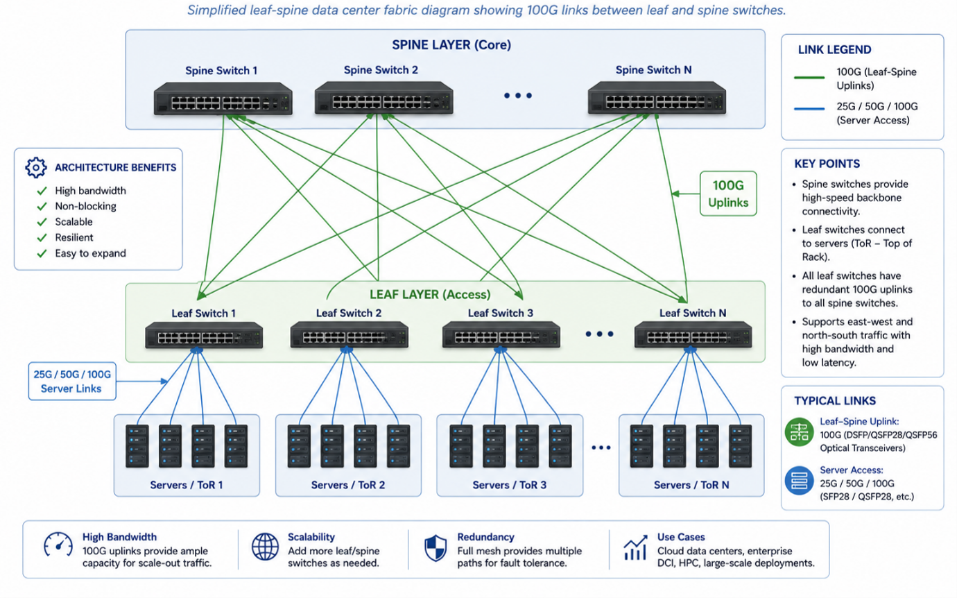
virtualized server environments. In cloud computing environments, 100G links
form the backbone of leaf-spine fabrics that interconnect thousands of servers
with predictable, low-latency, non-blocking bandwidth.
AI
infrastructure relies heavily on 100G and higher-speed optics to interconnect
GPU clusters, where the volume of data exchanged during distributed model
training places substantial demands on both bandwidth and latency. Storage
networks, particularly those adopting Ethernet-based protocols such as NVMe
over Fabrics, use 100G links to keep pace with the throughput capabilities of
modern NVMe storage devices. Within data centers broadly, 100G has become the
standard leaf-spine and server-uplink speed for most new deployments as of the
current period, with 400G increasingly used for spine-to-spine and core links.
In
telecommunications, 100G optics support core and aggregation network links,
often using longer-reach variants such as ER4. 5G network rollouts depend on
100G (and increasingly higher-speed) links for backhaul and fronthaul
connectivity between cell sites, aggregation nodes, and core networks, given
the substantially increased data volumes associated with 5G radio access. Internet
Service Providers deploy 100G links at peering points, in core routing
infrastructure, and in metro aggregation networks. Metro networks commonly use
CWDM4, LR4, or ER4 optics to interconnect facilities across a city or region,
while campus networks frequently use LR4 or FR optics for building-to-building
connectivity across a corporate or university campus.
High
performance computing clusters use 100G and higher-speed interconnects for both
storage and compute fabric traffic, and financial networks, where transaction
latency has direct business impact, rely on low-latency 100G links for trading
infrastructure and data replication between sites. Healthcare organizations use
100G connectivity to support large medical imaging data transfers and
increasingly data-intensive electronic health record systems, while government
networks deploy 100G links in secure data center and inter-agency connectivity
contexts where reliability and standards compliance are paramount.
How
to Select the Correct 100G Module
Selecting
the appropriate 100G optical transceiver requires evaluating several
interdependent factors rather than any single criterion in isolation.
·
Distance is typically the first consideration. Links under 100
meters over existing multimode fiber are well served by SR4, while single-mode
links up to 500 meters can use PSM4 or DR, links up to 2 kilometers can use
CWDM4 or FR, links up to 10 kilometers require LR4, and links up to 40
kilometers require ER4.
·
Existing fiber type in the facility often constrains the decision further. A
site with only multimode fiber already installed will generally favor SR4 to
avoid a costly fiber plant upgrade, whereas a site with single-mode fiber, or
one being newly constructed, has more flexibility to select from PSM4, CWDM4,
LR4, DR, or FR based on distance and budget.
·
Connector and
cabling infrastructure should be assessed
alongside fiber type, since MPO-based parallel modules (SR4, PSM4) require
different patch panel and trunk cable infrastructure than LC-duplex-based
modules (CWDM4, LR4, ER4, DR, FR).
·
Budget considerations typically favor SR4 for the shortest links
due to lower-cost VCSEL and multimode components, while single-mode WDM-based
options such as CWDM4, LR4, and ER4 carry progressively higher costs as reach
and laser sophistication increase; DR and FR, being newer single-lane PAM4
designs, often present a favorable balance between cost and future
compatibility for new deployments.
·
Future expansion plans should factor into module selection, since
organizations anticipating a migration toward 400G or 800G Ethernet may prefer
DR and FR modules, as their single-lane PAM4 architecture aligns more directly
with the building blocks used in higher-speed breakout configurations, easing
future transitions.
·
Switch
compatibility must be verified against the
specific switch platform and firmware version in use, including confirmation of
vendor coding requirements as discussed in the compatibility section above.
·
Power consumption varies meaningfully across module types, with SR4 typically
the lowest and ER4 typically the highest due to its amplification and APD
receiver components; this should be checked against the switch's per-port power
budget, particularly in high-density deployments.
·
Operating
temperature range should be
confirmed against the deployment environment, since standard
commercial-temperature modules (0°C to 70°C) may be insufficient for outdoor
cabinets or extreme environments, which instead require industrial or
extended-temperature-rated modules.
·
Reliability considerations include confirming that the selected module
has undergone appropriate qualification testing, and that the vendor provides
adequate warranty and technical support, particularly important for
mission-critical infrastructure.
A
typical hyperscale leaf-spine deployment might use 100G SR4 modules for
server-to-leaf connections within a rack row where cable runs remain under 70
meters over existing OM4 fiber, while using CWDM4 or LR4 modules for
leaf-to-spine links that traverse longer distances across a data hall on
single-mode fiber. A metro data center interconnect scenario linking two
facilities eight kilometers apart would typically deploy 100GBASE-LR4 modules
over dedicated or leased dark fiber, taking advantage of LR4's 10-kilometer
IEEE-standardized reach with margin for connector and splice losses.
Best
practices for 100G optical deployments include verifying end-to-end optical
loss budgets before installation, particularly for longer-reach modules such as
ER4 where link margin is tighter; maintaining strict cleanliness protocols for
fiber connectors, since contamination is one of the most common causes of
intermittent link errors; using DDM data continuously to monitor transmit
power, receive power, and temperature trends that may indicate a degrading
module before it fails outright; and standardizing MPO polarity schemes across
a facility to avoid the common error of mismatched Type A/B/C cabling during
parallel-optics deployments.
Common
mistakes include deploying SR4 modules over OM3 fiber at distances exceeding
the reduced 70-meter reach supported by that fiber grade, mismatching MPO
connector gender or polarity type across a link, failing to verify that a
switch platform's firmware version supports the specific transceiver's vendor
coding, and neglecting to account for connector and splice losses when
calculating whether a link falls within a module's specified optical budget.
Troubleshooting
a non-functional 100G link should generally begin with reviewing DDM data for
abnormal transmit or receive power levels, followed by inspecting and cleaning
fiber connectors at both ends, verifying that fiber polarity is correctly
mapped end-to-end, confirming that the transceiver type matches at both ends of
the link (mismatched module types will not interoperate even if physically
compatible), and checking switch logs for module identification or firmware
compatibility warnings.
Cost and Standards Considerations
While
pricing varies by vendor and market conditions, a general cost hierarchy exists
across 100G module types, generally increasing from SR4 as the lowest-cost
option, through PSM4 and DR, to CWDM4 and FR, and finally to LR4 and ER4 as the
higher-cost options, reflecting the increasing sophistication of laser
technology, wavelength multiplexing components, and, in ER4's case, optical
amplification required to achieve extended reach.
It
is worth noting that some specifications differ subtly between
IEEE-standardized modules and MSA-defined modules. For example, 100GBASE-LR4 is
an IEEE 802.3ba standard with tightly defined optical budget parameters subject
to formal standards compliance testing, whereas CWDM4, PSM4, and similar
MSA-defined modules are governed by industry consortium specifications that,
while widely adopted and generally interoperable across compliant vendors, do
not carry the same formal IEEE standards body oversight. Engineers specifying
mission-critical links where formal standards compliance is a procurement
requirement should confirm which category, IEEE-standardized or MSA-defined,
applies to their selected module.
JTOPTICS® 100G Solutions:
JTOPTICS®
provides a broad portfolio of optical connectivity products designed to support
data center, enterprise, and telecommunications networks, including 100G
optical transceivers across SR4, PSM4, CWDM4, LR4, ER4, DR, and FR variants,
direct attach copper (DAC) cables, active optical cables (AOC), MPO/MTP trunk
and harness solutions, fiber patch cords, and broader data center and
enterprise networking connectivity solutions. Network engineers and procurement
teams evaluating 100G connectivity options can use the technical framework
outlined in this guide, distance, fiber type, connector infrastructure, switch
compatibility, power budget, and future expansion plans, to identify the module
type best suited to their specific deployment.
Frequently Asked Questions
1. What is the difference between 100G QSFP28 and 40G QSFP+? QSFP28 and QSFP+ share the same mechanical footprint, but
QSFP28 supports four electrical lanes at 25 Gbps each (100G aggregate) compared
to QSFP+'s four lanes at 10 Gbps each (40G aggregate).
2. Can a 100G QSFP28 module be used in a 40G QSFP+ port? No. While the mechanical form factor is compatible, the
electrical signaling rates differ, and the switch ASIC and port must explicitly
support 100G QSFP28 operation.
3. What is the maximum reach of 100G SR4? 100GBASE-SR4 supports up to 100 meters over OM4 multimode
fiber and approximately 70 meters over OM3 multimode fiber.
4. Why does SR4 use an MPO connector instead of LC? SR4 transmits four separate optical lanes on four separate
fibers without wavelength multiplexing, requiring eight total fibers, which is
efficiently served by a multi-fiber MPO-12 connector.
5. What is the difference between CWDM4 and LR4? Both use four CWDM wavelengths over a single fiber pair,
but LR4 is an IEEE 802.3ba standard engineered for 10 km reach using EML
lasers, while CWDM4 is an MSA specification typically supporting 2 km reach
with simpler and lower-cost optics.
6. Is PSM4 single-mode or multimode? PSM4 uses single-mode fiber, despite using a parallel-lane
architecture similar to the multimode SR4 module.
7. What connector does 100G LR4 use? 100GBASE-LR4 uses an LC duplex connector, since all four
wavelengths are multiplexed onto a single fiber pair.
8. What is the maximum distance of 100GBASE-ER4? 100GBASE-ER4 supports reach of up to approximately 40
kilometers over single-mode fiber.
9. What is the role of a DSP in a 100G transceiver? A DSP performs equalization, forward error correction, and
clock recovery functions, which are particularly important in longer-reach or
PAM4-modulated optical designs to maintain signal integrity.
10. What is Digital Diagnostic Monitoring (DDM)? DDM is a set of real-time module telemetry parameters,
including transmit power, receive power, laser bias current, temperature, and
supply voltage, that allow network operators to monitor transceiver health and
detect degradation before failure.
11. Why do some switches reject third-party transceivers? Many switch vendors implement a vendor ID check against
data stored in the transceiver's EEPROM; if the module's coding does not match
an approved list, the switch may issue warnings or, in some configurations,
disable the port.
12. Does third-party EEPROM coding change optical
performance? No. Compatibility coding only
modifies identification data read by the host platform; it does not alter the
underlying optical or electrical specifications of the module, which remain
governed by the applicable IEEE or MSA standard.
13. What is the difference between APD and PIN photodiodes? A PIN photodiode provides straightforward
optical-to-electrical conversion suited to shorter, higher-power links, while
an APD provides internal gain, improving receiver sensitivity for longer-reach,
lower-power-budget links such as ER4.
14. Can 100G DR and 400G modules be used interchangeably? No, though DR's single-lane, single-wavelength PAM4
architecture is conceptually related to the building blocks used in some 400G
breakout configurations, DR and 400G modules are distinct products with
different aggregate data rates and are not interchangeable.
15. What fiber type is required for 100GBASE-DR? 100GBASE-DR requires single-mode fiber and uses an LC
duplex connector, supporting up to 500 meters of reach.
16. Is OM3 fiber suitable for 100G SR4 links longer than 70
meters? No. OM3's modal bandwidth limits
100GBASE-SR4 reach to approximately 70 meters; longer distances on OM3 fiber
will exceed the module's supported optical budget and may result in unreliable
link performance.
17. What is the significance of MPO polarity types A, B, and
C? These define standardized fiber
position mapping schemes between the two ends of an MPO-based cabling system,
ensuring transmit and receive fibers align correctly across trunk cables, patch
panels, and modules in a complete optical channel.
18. Which 100G module is best suited for a data center
interconnect at 2 kilometers? Both 100G CWDM4
and 100GBASE-FR are well suited to 2-kilometer single-mode links; FR's
single-lane PAM4 architecture may offer better long-term alignment with future
higher-speed migration paths.
19. Do all 100G modules use the same host electrical
interface? Most legacy 100G QSFP28 modules use
four electrical lanes at 25 Gbps NRZ, but newer modules such as DR and FR may
use different electrical lane configurations depending on host SerDes
capability, so compatibility with the specific switch ASIC generation should be
verified.
20. What operating temperature range should be specified for
outdoor cabinet deployments? Standard
commercial-temperature modules rated for 0°C to 70°C are generally insufficient
for outdoor or extreme-environment cabinets, which typically require industrial
or extended-temperature-rated transceivers instead.
21. How does CMIS differ from earlier SFF-8636 module
management? CMIS (Common Management
Interface Specification) is a newer, more flexible management interface
standard that supports advanced module features and higher-speed applications
beyond what the earlier SFF-8636 specification was designed to accommodate, while
remaining backward compatible in many implementations.